





1904 Whitehead Vertical Gas Engine

Started by Jasonb · 54 replies · 3,113 views

Jasonb
23 Aug 2026, 18:52
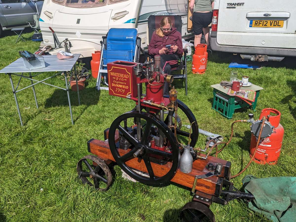
I’m not sure when this engine first caught my eye but I have had this photo in my “Future Projects” folder for some time.


There is very little information to be found for Whiteheads or any of their engines. The “A-Z of British Stationary Engines” does have it listed with a copy of this illustration and a summary of the text.


I have been unable to find any views showing other sides of the engine and asking around on the Stationary Engine Groups, it appears they are very rare, the one in the photo is said to have been reconstructed from just a few remaining original parts and it is said there is another more original engine but that is not shown in public. After making a start I did find a short video but once again taken from the same position.

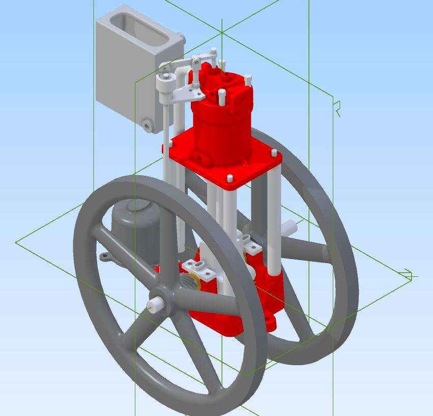
I made a start on the design by importing the image into Alibre and scaling it to suit 230mm flywheels which works out at just a bit larger than 1/3rd scale. There had been a few comments on the FB Groups that other may be interested in making one so I designed it with using castings for the flywheels and base in mind. This is the basic design with a few of the smaller details to be added as work progressed.


Starting with the patterns. To reduce the amount of cutting time on the CNC and also to get a more stable pattern the basic shape was glued up from strips of hardwood and stuck to a piece of MDF with a sheet of paper in the joint which makes it easy to remove from the MDF once complete.
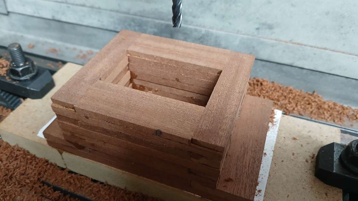


The roughing cuts were done with a 6mm long reach flat ended cutter, 8mm DOC followed by a 1mm stepdown which leaves a contoured look.
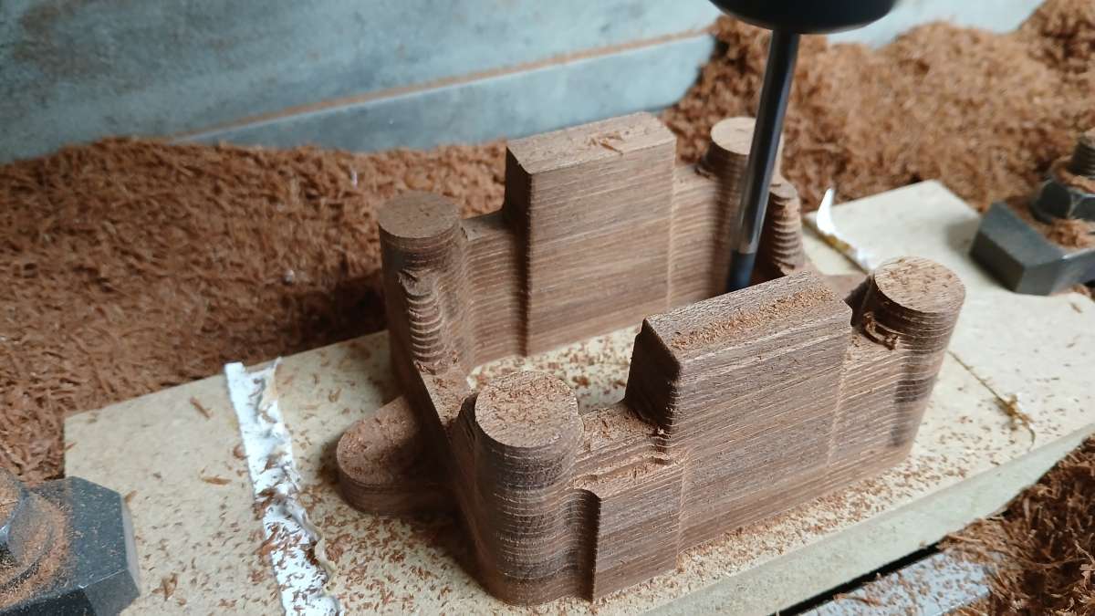


Then a swap to a long reach 4mm 4-flute ball ended cutter using a 0.25mm stepdown refined the surface, part way through, then complete. This finish only requires a very light sand to have it ready to paint.
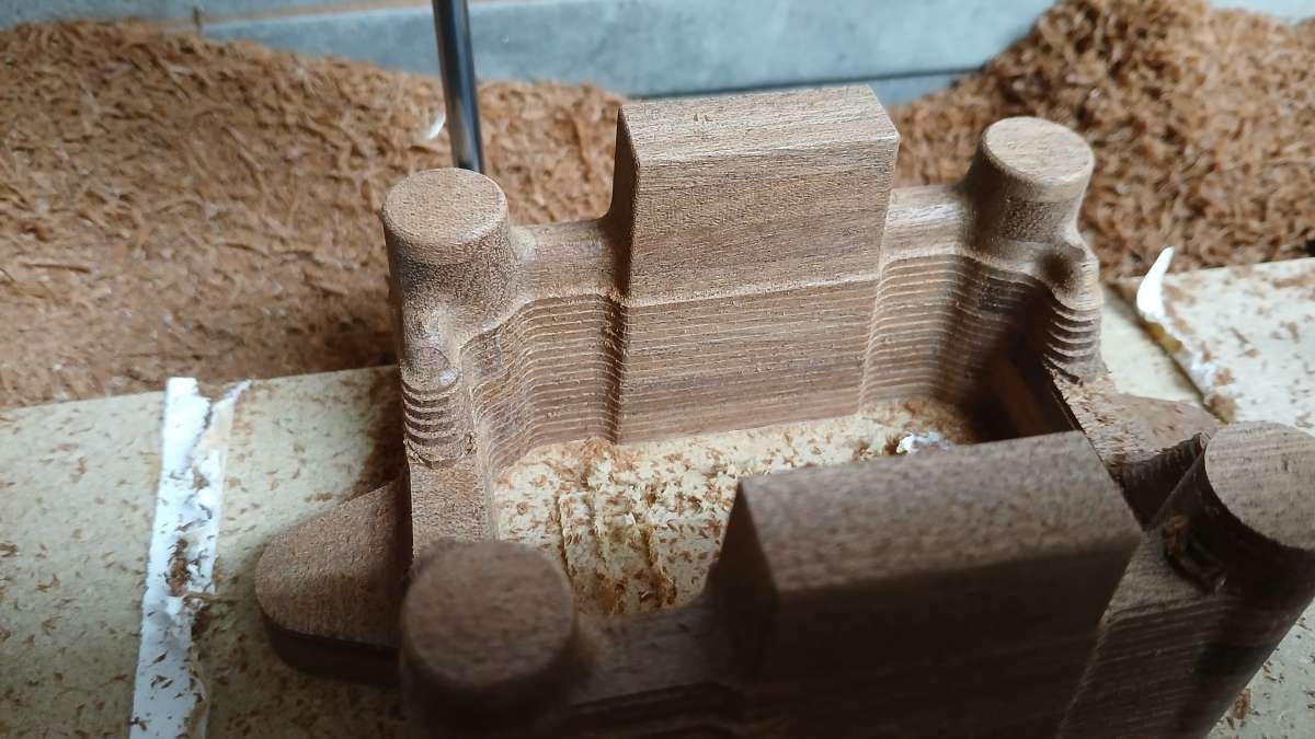
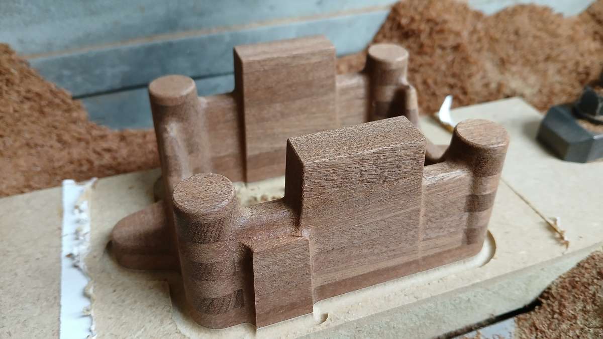


A quick blow with a chisel and the part is separated from the MDF base.
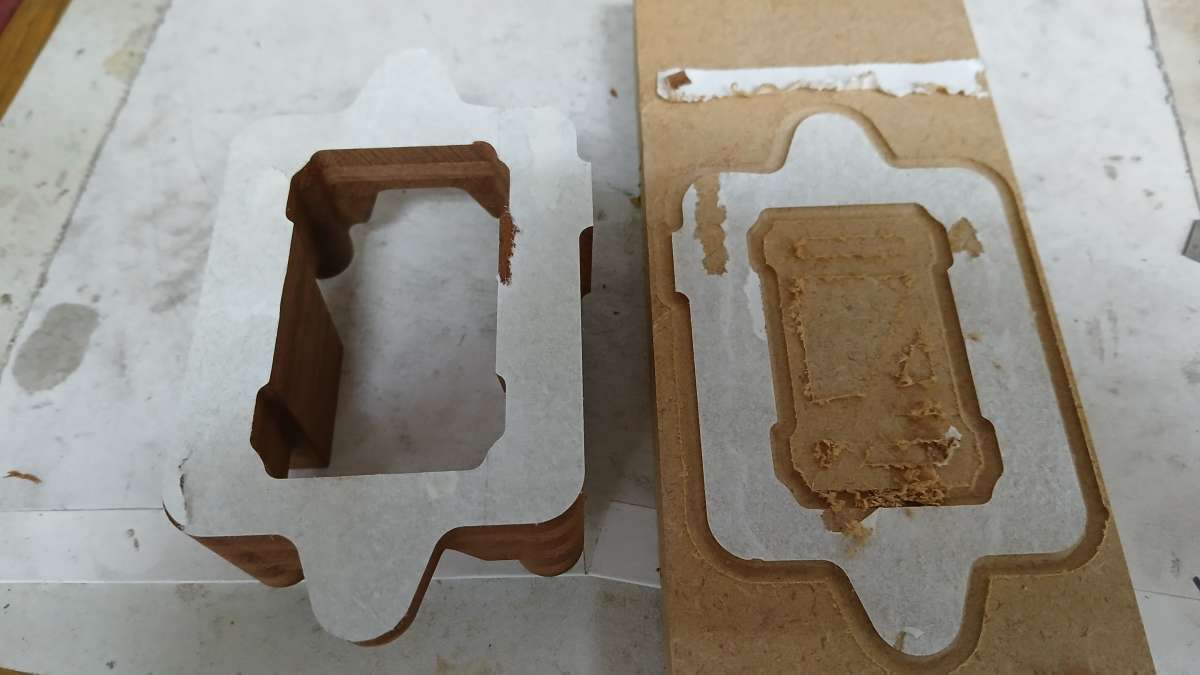


The flywheel was done in much the same way but as I did not have the Y travel each side had to be done in two halves, rotating the blank 180deg.
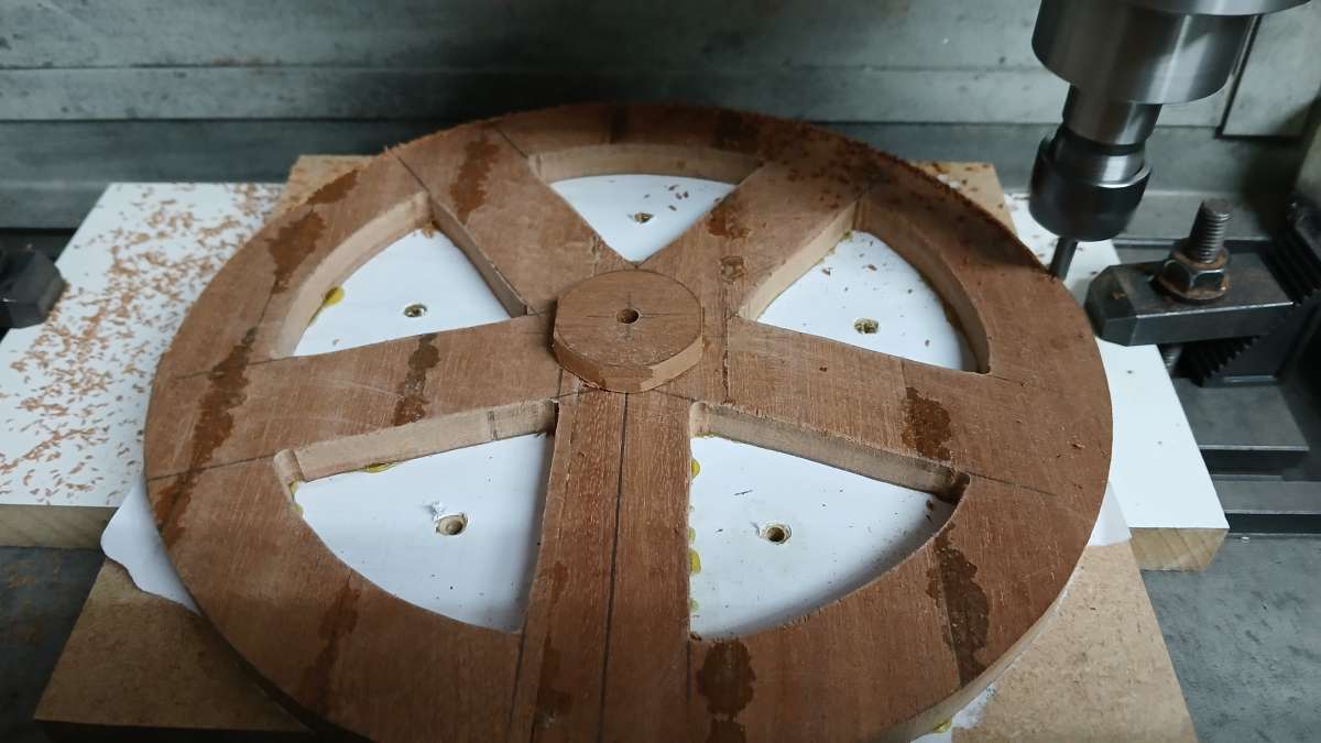
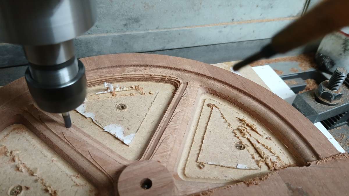
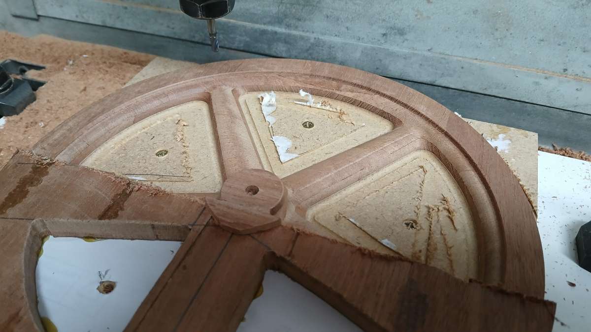


The Sapele that I used did not come from my usual source and after bringing the flywheel pattern inside a night of central heating caused it to warp. It went back flat after a few days in the workshop but I did not want to risk it moving in a hot foundry so decided to get patterns 3D printed in ABS, the base was OK.

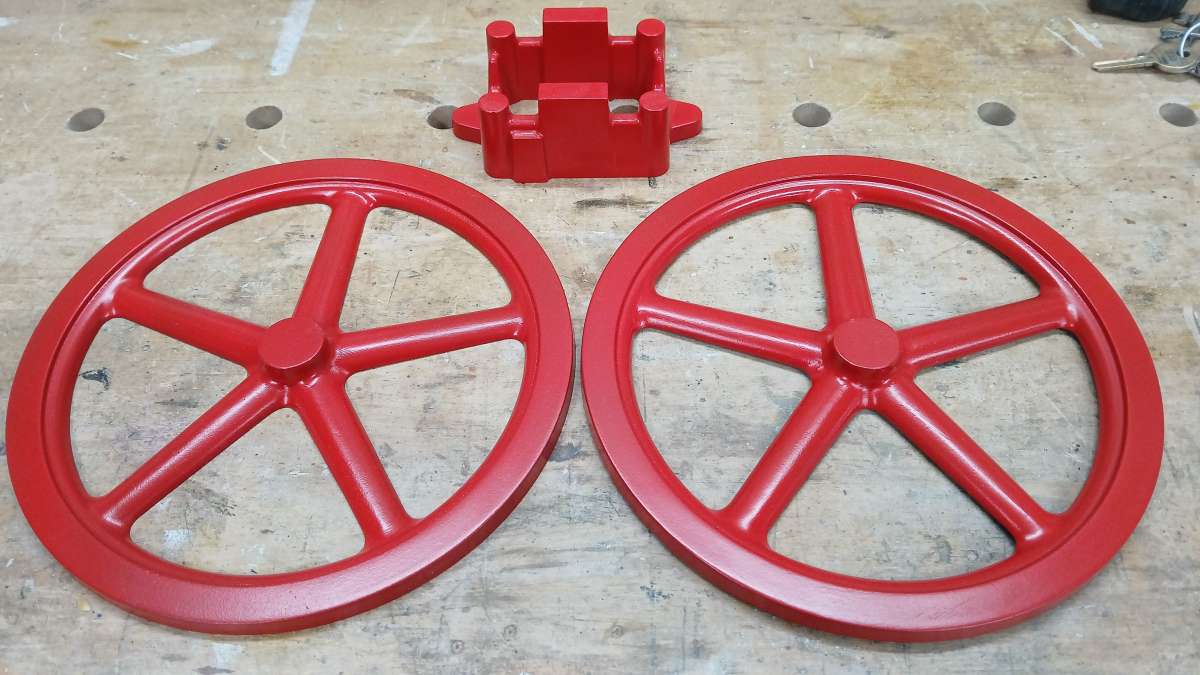
After a few hours sanding the printed pattern was good enough for several layers of High Build primer and then gloss. The base was a lot easier to get prepped & painted. Patterns ready to be sent off for casting.
redhouseluv
Reply #2 · 23 Aug 2026, 19:24
This is going to be an interesting one, so much progress already on a great looking unusual engine. I see the original advertising states it can be reversed how is that achieved?

It's going to be a fair size at 1/3 scale ............ following along  :popcorn: :ThumbsUp:
Jasonb
Reply #3 · 23 Aug 2026, 19:43
I'm hoping it will turn out to be a nice one too. Being quite an early engine it still has some of the look of a steam engine with its cylinder stood on the four columns which also means you can see all of what is going on rather then the more enclosed later engines.

They may have had a way to quickly change the position of the face cam on the top of the vertical cam shaft, much like you can change the direction of a steam engine with a slip eccentric.

It will end up about 350mm or 14" from the bottom of the flywheel to the top of the rocker arm. Alibre tells me it will weigh in the region of 8kg  or 18lbs so still comfortable to move about.
Chipswitheverything
Reply #4 · 24 Aug 2026, 07:36
Brilliant work on the CNC production of the patterns. The base is quite an intricate shape.    Pity about the movement of the wood after spending the time and effort on what should have been a very useable large flywheel pattern. As others have remarked, this is quite a hefty model engine ...
nj111
Reply #5 · 24 Aug 2026, 09:58
You achieved a very nice clean cut on the sapele with the ball end cutter. - I'm assuming on your CNC mill rather than on a CNC router?  For the record what spindle speed did you have available for those cuts?
Jasonb
Reply #6 · 24 Aug 2026, 10:03
Yes it is on the CNC mill which has a maximum speed of 5000rpm so a bit on the slow side for wood but gives a very acceptable finish
Dave Otto
Reply #7 · 24 Aug 2026, 14:55
It will be fun to watch this interesting, not a steam engine, come together.  ;)

Dave
Alyn Foundry
Reply #8 · 24 Aug 2026, 15:11
Blimey Jason, not a gas engine you’ll break the monotony!!  :lolb:

Looking forward to seeing the remaining progress.  :ThumbsUp:

We first spotted the advertisement over 40 years ago in an old bound copy of ME.  Vincent took a shine to the design but we never moved on it. Great to see a working model.

The next step will be to go direct lost PLA casting in Iron. Here’s a photo of a first attempt in SG iron moulded in Airset sand.

:cheers:  Graham.
Log in to see this image
Jasonb
Reply #9 · 24 Aug 2026, 15:47
Dave, I'm hoping to run it fast enough to get some steam off the cooling tank :lolb:

Graham. It would be interesting to try the lost PLA on a more complex casting that might otherwise have needed a core. From what I have seen of other peoples attempts the gasses from the burning PLA can cause problems. Your simple gears would have been a lot easier to vent.

But for parts like the flywheel and base I don't see an advantage in lost PLA over traditional methods where the pattern is removed.

I'll go and search the ME archive to see if I can find what issue it was in. I've also been studying the Boys Own mag these last few days ;) ;) ;)
Art K
Reply #10 · 24 Aug 2026, 20:48
Jason,
That looks to be an interesting very early GAS engine coming together! The option to run it backwards is probably made easier by having an atmospheric intake valve setup. Sounds like a fun build. I'm working on breaking the monotony of steam builds myself!
Dave Otto
Reply #11 · 24 Aug 2026, 20:55
Quote from: Art KJason,
That looks to be an interesting very early GAS engine coming together! The option to run it backwards is probably made easier by having an atmospheric intake valve setup. Sounds like a fun build. I'm working on breaking the monotony of steam builds myself!


Me too! :)

Dave
rdean33422
Reply #12 · 24 Aug 2026, 23:12
I'm actually going the other way as I have 22 internal combustion engines that I have built and I am now building steam engines.

Ray
Jasonb
Reply #13 · 25 Aug 2026, 05:51
If you based IC engine builds on the number of cylinders then this forum is fairly balanced as the V8s would outnumber the single and twin cylinder steam engines. :LittleDevil:

I Like a bit of everything. This month I have drawn up a compound steam engine and two single cylinder IC engines plus finalised a second small steam engine design for which the whole set of 3D printed "castings" are in the air now on their way to me. I just can't build them at the rate I draw them and can't draw them at the rate I see something I fancy.

And there in lies the problem, it is what takes my fancy that gets made. I have had this engine and another eary IC engine sitting on the bench almost finished for several months but the draw of the steam engines has been stronger. I expect I will start on that 3D printed one as soon as the bits arrive and build it right through to completing, paint and running. The other early engine will have to wait a bit longer.
Michael S.
Reply #14 · 25 Aug 2026, 08:25
That’s an interesting engine design. So far, I’ve only built steam engines, two Stirling engines, and a flame-licker. I do have a casting kit for an internal combustion engine sitting under my workbench, though.
Jason, where do you find the time for so many engines? I’m happy if I manage to build two or three a year.

Michael

Quick reply

Log in to reply.