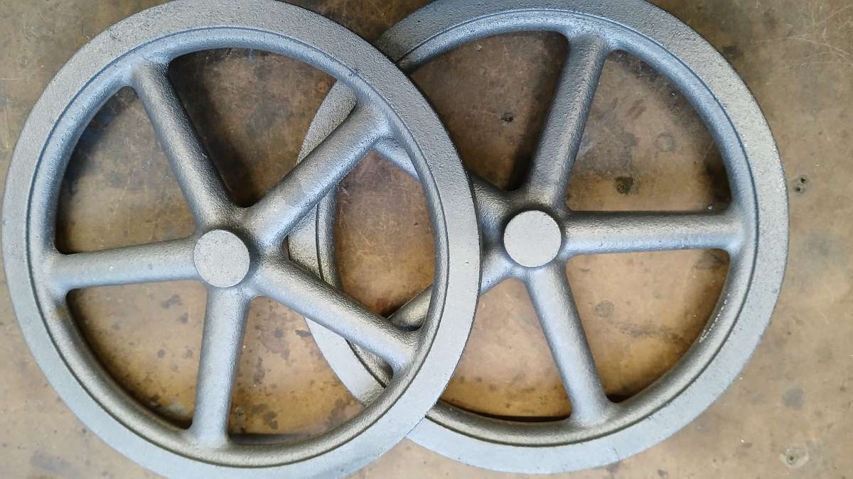
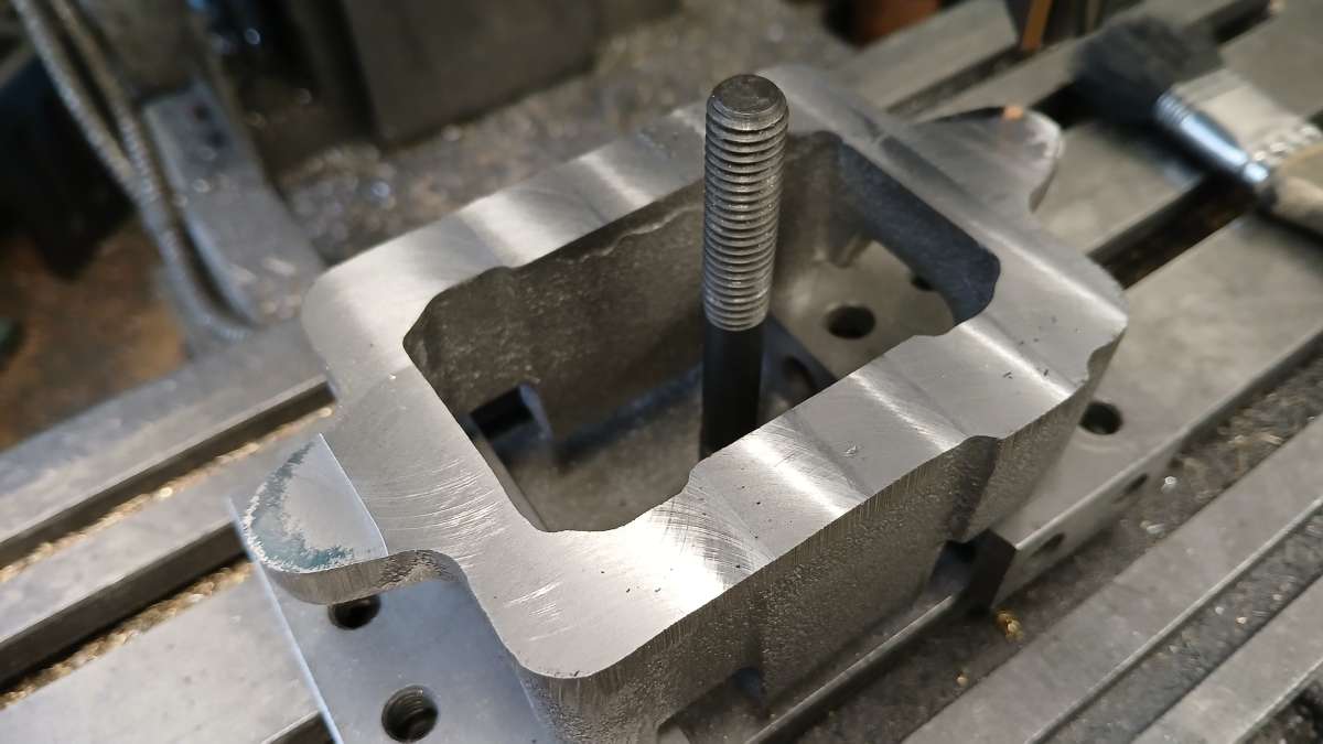
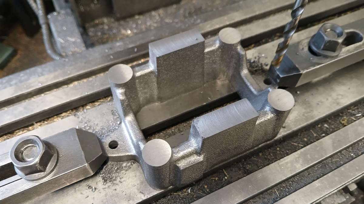
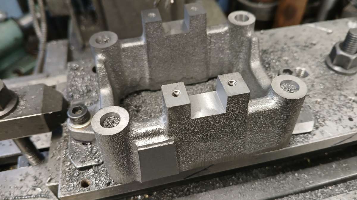
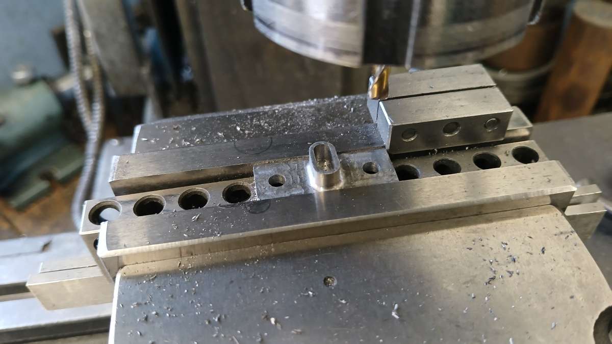
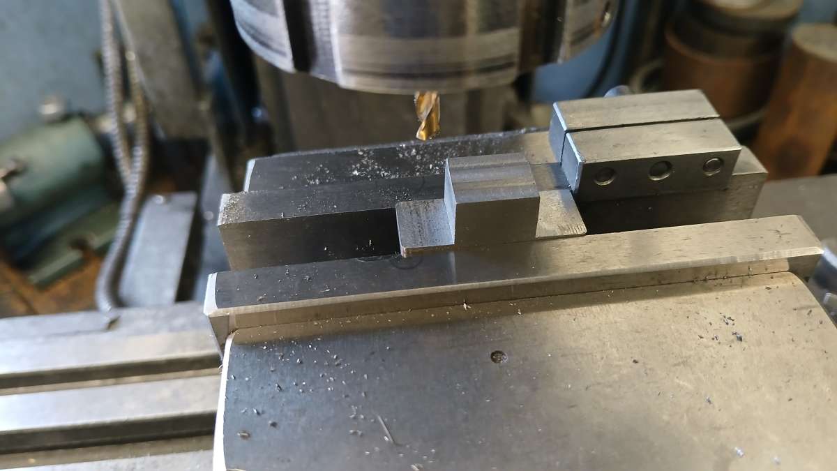
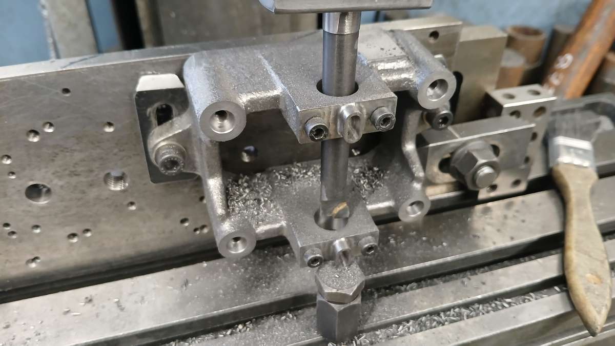
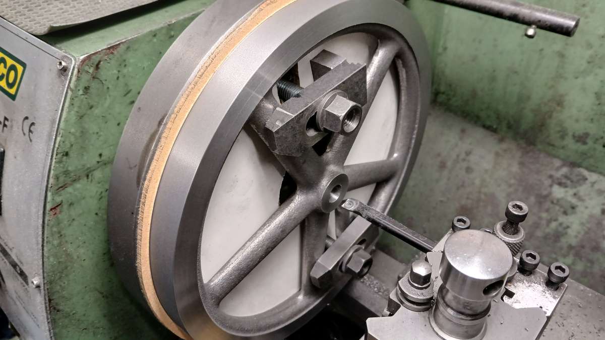
Not much to say about machining flywheels that I have not said before. Five Spoke layouts are always a pain to hold as you usually can't get 3 or 4 jaws inside the rim without the spokes getting in the way so I mount them on a faceplate with a bit of 6mm MDF between. That way I can completely turn the face, one side, the hub and bore all in one setup. The hub was bored using a piece of the 12mm PGMS that will form the crankshaft as a gauge.
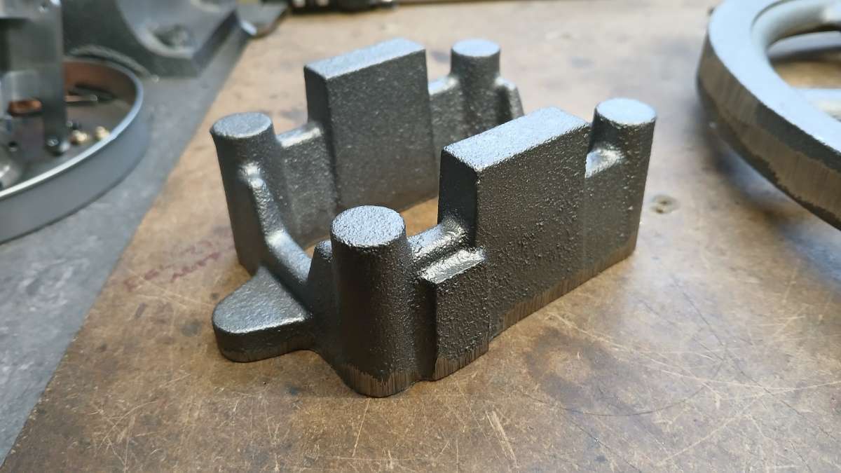
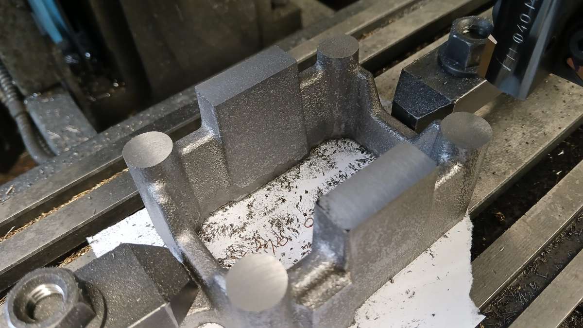
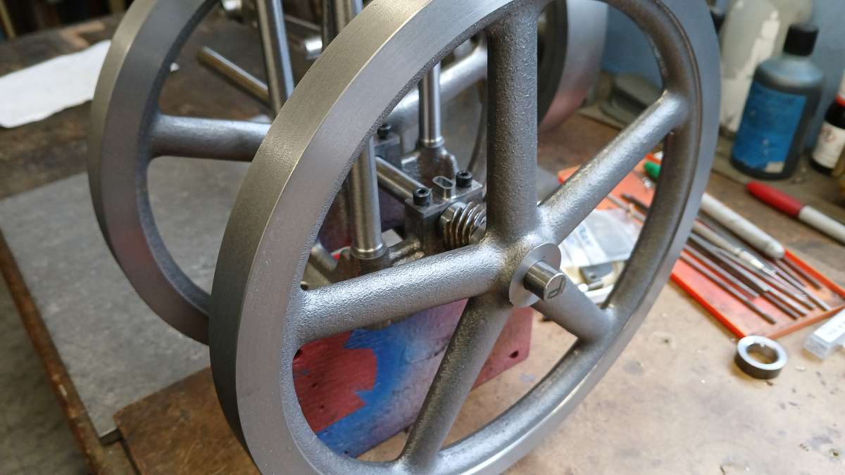
Here they are slipped into position to get a feel for how they will look. The columns have also been made which are just tapered shafts with threaded spigots on the ends.
The cylinder jacket started life as a piece of 55mm dia EN3 and was roughed out to shape, the short spigot on the end will locate in the entablature plate.
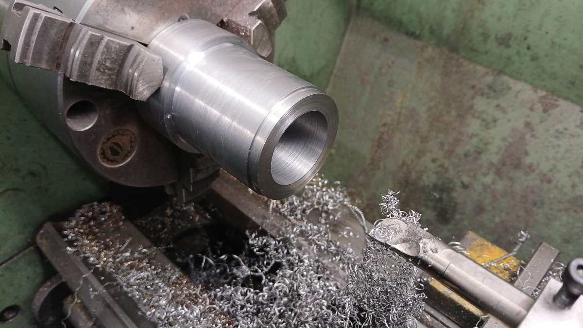
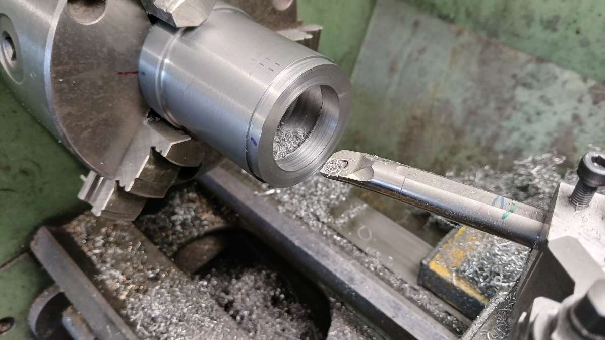
With the boring bar held at an angle and coming in from both ends the middle was hollowed out to form the water space
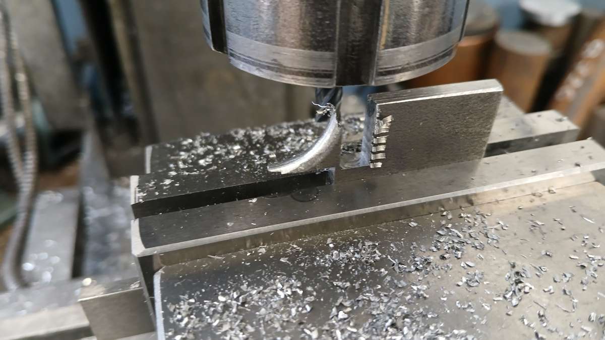
There are two small webs at the base of the water jacket, these were formed on the corner of some 5mm plate and then the mill used to cut them from the plate.
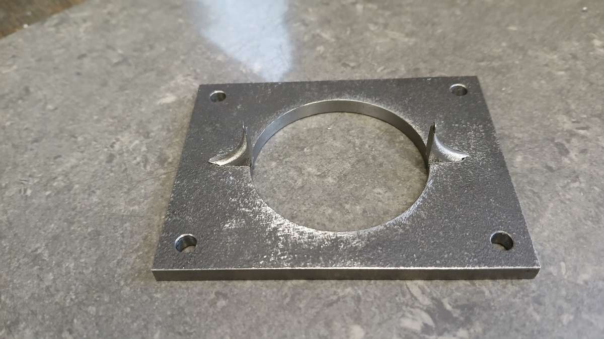
Here they are stood in place on the entablature plate which was cut from over thickness 6mm material, drilled and the central hole bored to accept the cylinder jacket.
The water bosses had there oval profile cut on the CNC, a boring head was used to do the concave cuts to suit the jacket and a holes drilled so they could be screwed in place to solder.
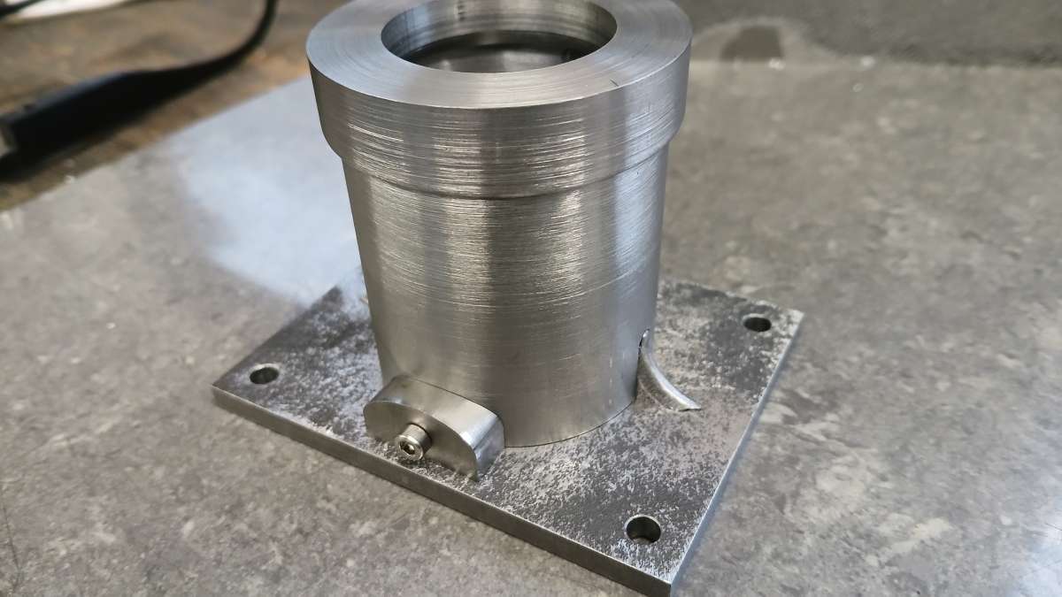
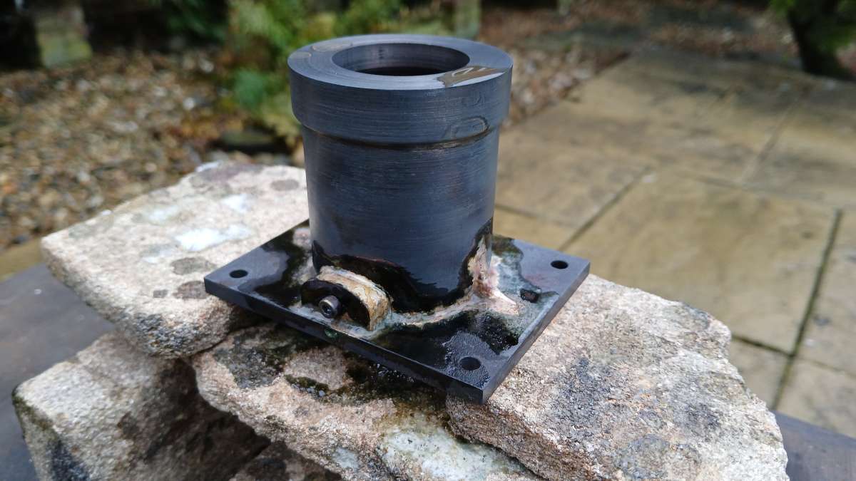
After a pickle the bottom of the entablature plate was faced down to it's final 5mm thickness.
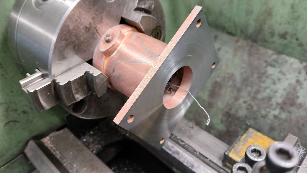
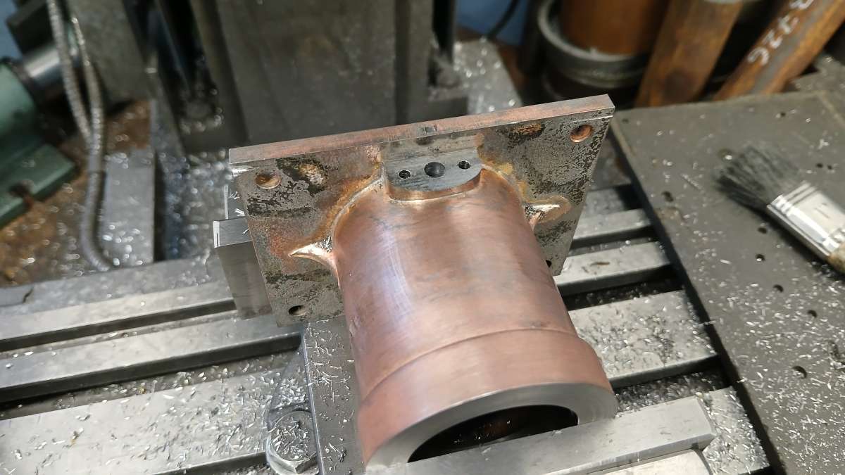
Then the top was faced to length, both ends bored for the liner and although it is hard to see there is a 1.5mm x 1.5mm rebate to take the lip of the liner.
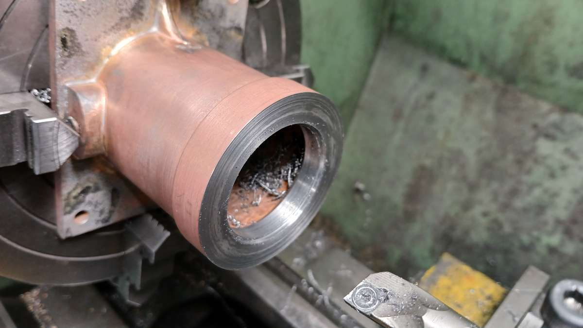
Lastly the water bosses were milled off flat, drilled for water and tapped for the flange studs. I must have drilled and tapped for some cylinder head studs too but did not take a photo.