Been off working on other stuff around the house, some writing, some CAD work, other events, but time to get back into the model shop again. This time I will be starting on the model of the paddlewheel engine from Isambard Kingdom Brunel's (yes, the guy you always see in front of the huge chains while wearing a top hat big enough for 3 shop elf apartments) first ship, the Great Western. This was his first ship after a career built on LOTS of railroad/bridge/tunnel work. The engine was a side-lever design built by Maudslay, Son, and Field. It had two cylinders, each with 73-1/4" (or another similar dimension, depending on which book you read) bore and 7' stroke - huge cylinders to compensate for the low boiler pressure they ran to avoid scaling the inside of the boilers with the seawater they added to the supply during the voyage. Frequent blowdowns to remove scale too - this was common on early ocean-going ships until better condensers and more efficient engines let them run the higher pressures common on locomotive and factory engines of the day. The ship was launched in 1837, and was one of the biggest of its day.
The engine has a fancy gothic style cast iron frame with lots of arches and mouldings, so its a real looker. All the gothic styling, great on a stone building, did not work as well with all the twisting/rocking motions of the engine and ship, and they did have to repair cracks in the frame in the early voyages, but after that it held up well. Here is a rendering from the CAD model I drew:
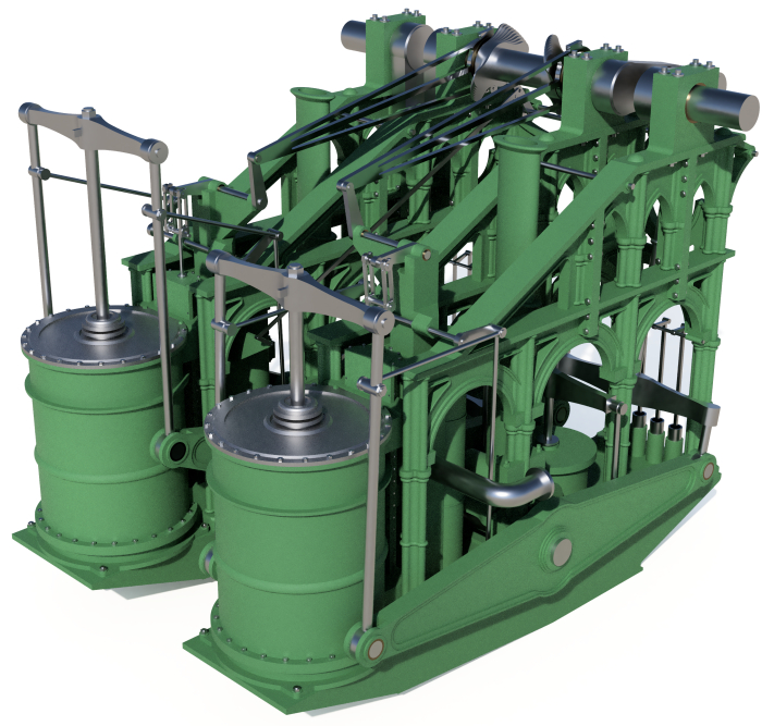
Each cylinder has its own frame and pair of side levers. At the far end of the engine are some cross-braces to connect the frames, and they were also braced to the hull top and bottom. The crankshaft at the top was at the level of the paddlewheel, and was directly connected. Though many other ships had some sort of clutch mechenism to disconnect the engine from the paddlewheels, Brunel opted not to include that feature since he intended the ship to use the engine for its primary propulsion on transatlantic voyages, though the ship still had four masts for sail assist. At this time, steamships capable of crossing the Atlantic under steam power were still a new thing.
Underneath the engines are condenser tanks, with an air pump just aft of the beam pivot, and there are other smaller bilge and feedwater pumps at the aft end. This engine still used the slip-eccentric setup for reversing, and it has a set of cams and levers to allow the engineer to control the cutoff of steam to the cylinders.
Should be a fun one to model! The fancy frames presented the biggest challenge, and the intricate details and curves drove me to cut the frame sections on my little CNC machine, something I resist in most models since I find it kind of boring - set it up, hit go, and walk away for a long time, then set up for the next part. I much rather to do the machining manually, but for these shapes it was just not that practical. So, the frames will be cut by CNC, the rest will be my usual manual machining.
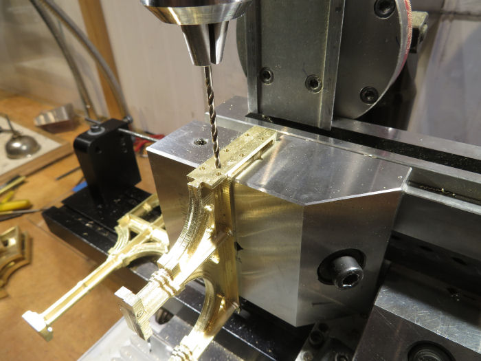
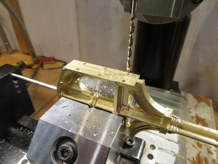
Over the last week or so I've had the CNC nibbling away at flat bars of brass. Since the frames are shaped all the way around, and getting the second side aligned well would have been difficult, I decided to make each frame section in left/right halves and rivet them together to make the final shapes. I started with the smallest frame sections, the sections of column that hold the side lever shafts - these sections bolt to each other to make the taller column piece, which then bolts onto the lower end of the front frame panel. Here I am drilling for rivets.
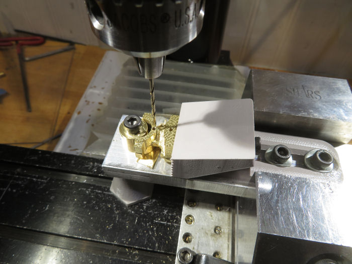
To align the halves, I pushed them against a round post with a clamp that I 3D printed from a design I found online. The clamp worked well, but one piece wound up splitting along the printed layers - I should have aligned the layers to be vertical on that piece to avoid the shearing forces on it. Each pair of parts was drilled in one go, then the holes were countersunk slightly with the tip of a center drill twisted by hand. This opened up the ends of the hole slightly, so the head of the rivet would expand into that tapered end, and not stick up above the surface of the part. I used some 1/16" brass rod as rivets, cut a little longer than the thickness of the two parts, and the ends smooshed over with a rivet squeezer I made some years ago. Then the final domes were flattened by hammering on the anvil.
Here is the first one done, next couple ready to go. There are four panels to make altogether, so 8 of each part were made (half mirrored from the other side). The upper/lower subassemblies were then drilled for 0-80 screws through the flanges around the bearing holes to hold them together.
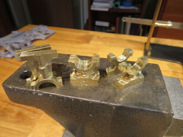
Since riveting is not really precise, I trued up the holes in the columns on the lathe after some careful alignment in the 4-jaw. Took off just a thin layer inside the holes to get them true and all the same diameter for adding the bronze bearings later on. The holes are .465" ID.
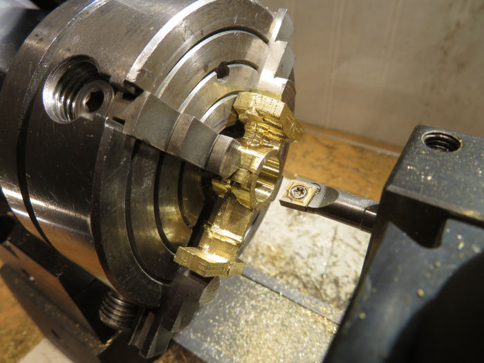
Here are the first pieces for the aft frames. On the real engine, the frame panels were divided into three sections that bolt together on vertical flat sections.
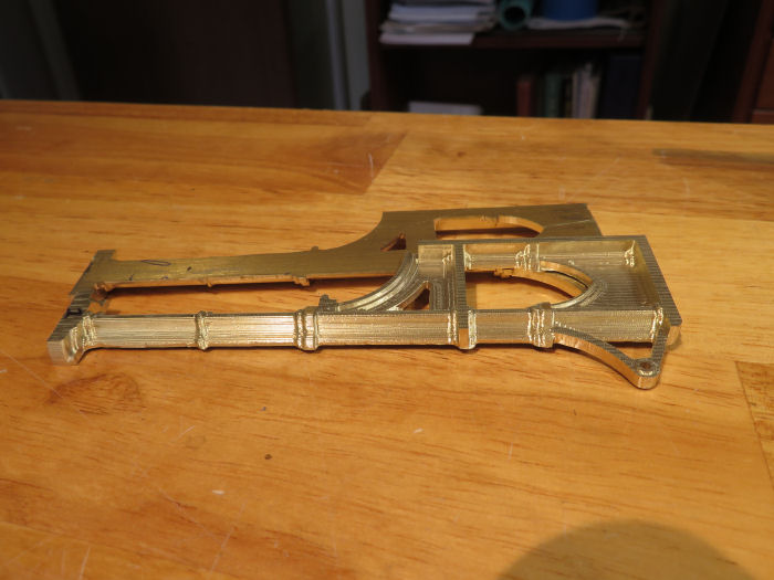
These were likewise drilled for rivets, after clamping each pair together and figuring out how to hold them in the vise:
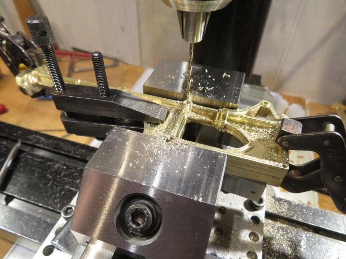
Same for the middle panels, which were easier to hold in the vise with thier flat sides
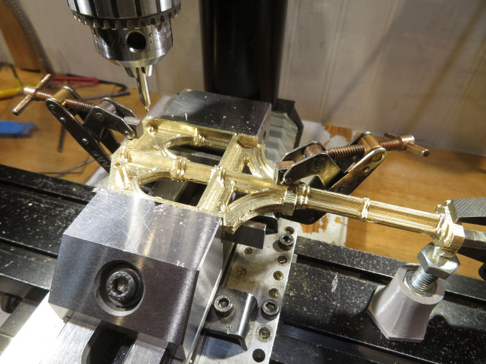
Then set up to drill the holes for the bolts to hold the read and middle sections together
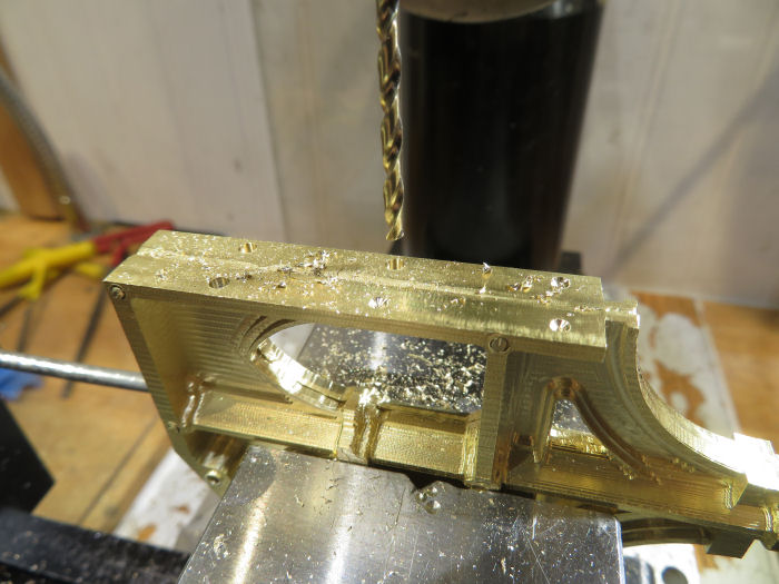
Here are the aft and middle panels assembled, with the first of the front panels stood in front of them. I am still waiting on the last set to mill on the CNC - will be able to continue the assembly work tomorrow, and will start CNC-ificating the cross panels tomorrow. Once the front panels are rivetted together, I can drill/tap for the screws to hold the side lever bearing columns to the bottom of them, and get the middle and front panels drilled/bolted to each other.
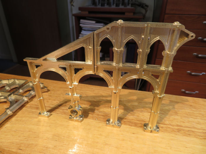
As you can see, its going to be quite a fancy looking engine. For reference, the panel assembly is 5-1/2" tall and 7" long overall. Off to a good start, though I will need to lock up these frame sections so the shop elves don't try to steal them for their pub - don't want them making the Elfminster Cathedral Tavern!
 And as you can imagine, cutting these sections out of 1/4" x 4" flat bar, I've got lots of new odd shaped pieces on the scrap pile that will get re-used for something, don't know what yet! Before starting the cutting, I had 3D printed samples of the panel shapes so I could experiment with the best way to nest all of them together to use the least material overall, and leave some useful shapes after the 'cookies' were cut from the 'dough'!