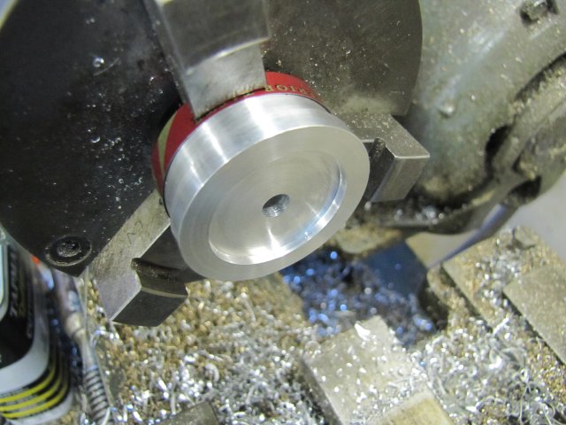
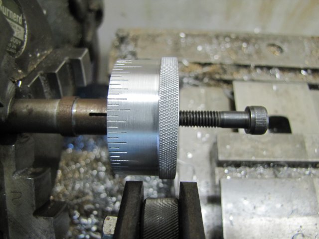
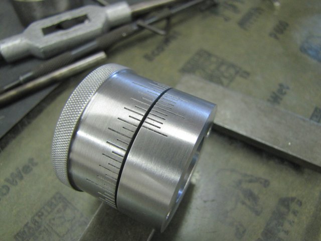
It's been quite a while since I posted up on any of my antics in the workshop. My work life has been absolutely bonkers for the last five months, and I just did not have time or energy left to do much. Some other issues also detracted - one of which is the arrival of a couple of Raspberry Pi computers and some local people wanting me to showcase what can be done with those. So some time went into getting intimately familiar with these little beasties - both on electronics and programming level. I'll post more on that in due course. This thread is somewhat related to the Pi projects though - there's some machining required, and all is not too well with my ML7 lathe.
My Myford ML7 is about 45 years old, and I'm the third owner as far as I'm aware. She's starting to show some signs of wear - most notably the classical "loose carriage toward the headstock" bit, and, more alarmingly, a LOT of backlash on the cross slide. There's no doubt a lot of wear on the lathe is down to me - the poor girl landed up with a complete newbie and I had to, and still, learn a lot of lessons along the way at the lathe's expense...
Of late, the backlash on the cross slide has become a real pain. A quick check a while ago showed 1mm (40 thou) of backlash on the cross slide. Part of that is due to wear on the "mazak" dial and the mechanisms behind it, but the feed nut is not too great either - at least 0.5mm (20 thou) of lash is in there after I took some measurements.
The easiest option to rectify at least part of the problem is to just replace the feed nut. After getting pricing online for a new one, I picked myself up off the floor. I can't remember if I fainted or went into a hysterical laughter session. 47 GbP for a feed nut, converted to a very weak Namibian Dollar and with the transport pricing still to be added is just ludicrous IMHO.
Next option - make one; it's not really a complicated part. So I disassembled the cross slide's feed mechanisms, and while testing the nut by hand on the feed screw, noticed that it's slightly better fitting on the parts of the feed screw that has seen less use, so the feed screw itself is not that hot anymore either.
Coupled with the wear on the back of the dial and on the mounting bracket, everything is just plain worn. Some bits are easy to fix with a new bush or spacer here and there, but by this time, I'd already decided to go the whole hog and re-make things to my taste.
A new 2mm pitch metric feed screw and -nut with some form of backlash adjustment, bearings instead of bushes, and while I'm at it, a resettable micrometer dial; one feature that I've wished for on many occasions.
Material selection isn't great; for the most part I'll use whatever I have lying around and the bearings were scrounged from an old printer. I did splurge on a proper bit of phosphor bronze for the feed nut. For the feed screw, I'll use stainless steel; it was either that or silver steel. I'll see how that works out.
I scratched around in my own documentation and asked Google for the dimensions for the mounting bracket for the cross slide, but couldn't find it anywhere, so I set out taking the measurements off the cross slide itself. This is one example where Marv's suggestion a couple of years ago to add a threaded hole to the height gauge arm came into it's own. A 4mm cap screw conveniently allowed me to zero on the top of the cross slide, and then take the measurements below this:

To overcome the looseness in the feed nut, I carefully wrapped a couple of even layers of PTFE plumber's tape around the feed screw to tighten it up and keep it as central and straight as possible to take the measurement.
After taking more measurements, I had a bit of C-o-C with the needed dimensions - not super-accurate, but good enough:

A block of 80x60x20mm aluminium that I got from the offcut bin at one of the local metal suppliers a while ago volunteered to make up the beginnings of the new bracket after some marking out:

While it was a solid block, I hollowed out the underside for clearance for the top of the dovetail on the cross slide:

Next, some cut-outs on the sides to accommodate the mounting screws:

Finally the mounting holes - both about 0.5mm over-size. This isn't sloppy work, but intentional, as the play in the holes are used to align the bracket with feed screw properly to the feed nut - the original mounting is built like this as well:

A quick trial-fit:

Checking from below that the dovetail clearance is good:

The bracket at that stage:

For the vertical bit of the bracket, I used some 60x10mm hot-rolled mild steel. One long edge was used as a reference to mark the center point of the feed screw, and a hole was drilled under size and carefully bored to 16mm, and then a circle faced away on the flat side to remove the crud and make things nice and parallel. This side will be mounted to the aluminium part made earlier:

How things will go together later, together with the two bearings I scrounged to fit in the bored hole:

To mount the plate to the aluminium part, I was torn between using two M5 or M6 screws or four M4 screws. I didn't want the screw heads to encroach too much on the center of the bit, as some more things will need mounting there, and, should the bearings I have not work out, that there is enough space to install slightly larger thrust bearings. So I opted for the four M4 screws - they are nicely out of the way, but will give about the same amount of strength as using two M6 screws. So I worked out a bolt pattern that wouldn't be too much of an eye-sore, and drilled and tapped for M4. A bit of clearance for the feed screw and retaining ring on the bearing was also added while I had everything clocked up on the mill:

The steel plate got the same treatment, except the holes were drilled for M4 clearance, and counter bored 7mm 4mm deep to recess standard M4 cap screws. This is the front face showing - the turned back face is at the bottom, as that must mate very flatly with the aluminium bracket:

Assembled thus far:


There's a LOT of rounding over to be done on these parts - in use, they will be in close proximity to a lot of movement of hands and knuckles, and at this stage skin will get taken off. There's more machining to do first though, so neatening it up will have to wait. Next up is the new feed screw - which will be quite an interesting job, as I've not screw-cut this coarse a thread on stainless steel before...
Kind regards, Arnold







 - said with a nod of the head to Zee who appears to be in a similar position.


 - Everything works smoothly and feels really good when operated. I mounted my trusted 0.01mm Mutitoyo dial indicator and checked things out:

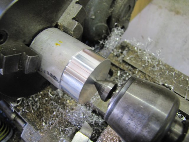
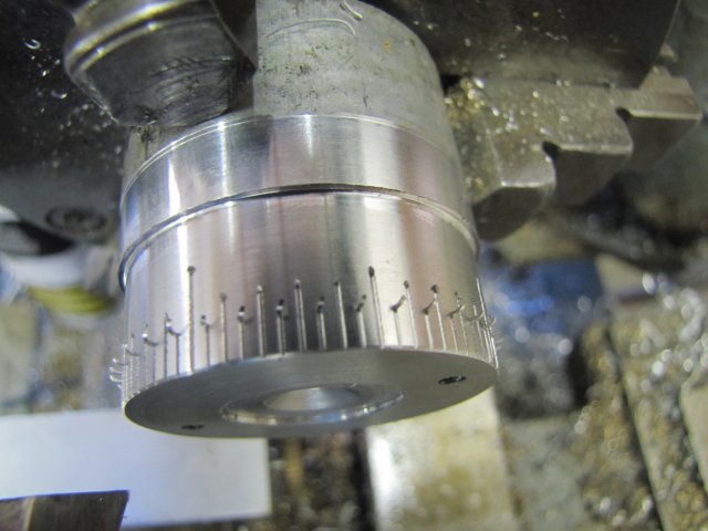
 - that's what one get by just eyeballing things.