An 1854 'A' frame engine: restoration

Started by redhouseluv · 55 replies · 1,826 views

Chipswitheverything
Reply #45 · 30 Oct 2026, 08:43
The unusual engine is running very nicely in the video clip, and sounds good too.  And the appearance is transformed from the rather gunky state in which it arrived, looks like an engineering artifact now!

I did a very minimal bit of marking out with bluing and scribing yesterday while machining the three slide valves for the triple, and was thinking , not for the first time, that the sight of a component marked out in the way that they once always used to be is quite a rarity now. So your crank shows that the tradition is still there!  Dave
redhouseluv
Reply #46 · 30 Oct 2026, 18:54
I find scribing gives me a good idea of where everything should be before I start

Everything was peachy when disaster struck, I had nearly completed the larger diameter and was cutting the middle out when the workpiece moved and the cutter took a nice chunk out of boss 😕

Instead of starting again I thought I’d see if I could recover it, so over to the lathe made a mandrel and machined the boss and put a chamfer on it. Then started machining the centre section and whilst I was at it, made a mandrel for the smaller hole and repeated the exercise.

I need to finish milling the smaller boss and then shaping the sides, I think I’ve got away with but let’s see!  ::) ;D
Log in to see this image
Chipswitheverything
Reply #48 · 31 Oct 2026, 08:51
Looking at the first photo, a bit surprised that you had that bit of bad luck, and a nasty moment!  - the three clamps on the job look like good clamping provision. S'pose it depends on how tightly they have been done up!  Looks like you may get away with the rescue ..
redhouseluv
Reply #49 · 1 Nov 2026, 01:25
Full disclosure, that’s what I couldn’t work out what had slipped; I think I reset the pins in each boss and forgot to tighten one up. So the clamps didn’t give, but the workpiece on the jig🤨

Live and learn! 😁

No more workshop updates from me for the next week or so, work has sent me away from family and workshop 😕
Jasonb
Reply #50 · 1 Nov 2026, 06:57
To me the clamps were not ideal

The rear one has the stud at the packer end of the clamp not near enough to the work so most of the force is going into the packer.

The left one is making contact with it's side not the end so will easily twist.

Right not too bad but can't really se it fully.

You need a traveling tool kit and a small restoration project to pass away those lonely evenings in the hotel.
redhouseluv
Reply #52 · 1 Nov 2026, 12:56
Quote from: JasonbTo me the clamps were not ideal

The rear one has the stud at the packer end of the clamp not near enough to the work so most of the force is going into the packer.

The left one is making contact with it's side not the end so will easily twist.

Right not too bad but can't really se it fully.

You need a traveling tool kit and a small restoration project to pass away those lonely evenings in the hotel.


It was after I fixed the work to the jig that I realised I’d should have more room all round to clamp it in place on RT. I’ll make a bigger one milling the smaller end and should get a firmer hold

No micro lathe unfortunately but I’ve packed some reading material 😀
Log in to see this image
crueby
Reply #53 · 1 Nov 2026, 13:49
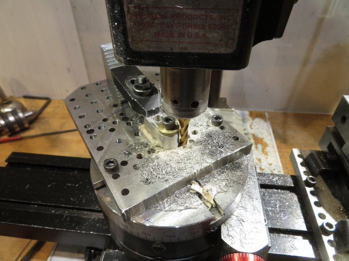
If there is a good way to fix one to your rotary table top, a larger steel plate with rows of threaded holes in it is super handy. I made one for mine years ago, use it all the time. I drilled all the holes back then, have been tapping the holes as needed (got tired of tapping that many pretty quick!)
redhouseluv
Reply #54 · 1 Nov 2026, 14:36
Now that looks far more rigid, I like it; I’ll need to invest in a steel plate as all I have in that sort of thickness is Ali
crueby
Reply #55 · 1 Nov 2026, 15:04
Quote from: Sanjay FNow that looks far more rigid, I like it; I’ll need to invest in a steel plate as all I have in that sort of thickness is Ali
Yeah, steel is much better, the threaded holes in ali tend to open up and wobble with many multiple uses. On my rotary table there is a center hole, so I made a post that screws into the bottom of the plate that is a close fit on that hole, to center the tooling plate. That post screws in with a screw that only comes halfway through the plate, so I can still use that hole from the top to screw down other jigs and have them centered on the rotation. The rotab has t slots, so I use a couple screws with t nuts to secure the table to the rotab. All depends what your rotab has on top for how you affix it. When doing long parts (reverse linkgs, conrods) I'll put the table down offset to one side to get more distance for clamping. Other times I'll have the plate centered.

Quick reply

Log in to reply.