Liney RV-2 Rescue

Started by Jasonb · 18 replies · 1,244 views

Jasonb
6 Oct 2026, 15:46
I got an email a few weeks ago from an internet friend asking if I wanted a part built engine that he had going spare. Now I use the word "Friend" in the broadest terms, as I don't think a real friend would have dared to give me an engine with so many interesting additional machining features that the original builder had included, but it certainly turned out to be the gift that kept on giving in that respect. :wallbang:

His email included a couple of images of the drawings which did not have the engine name or who designed it as well as some images of what he had. The story is that a friend of his bought them from a guy in America who had started to build ten engines and as they were cheap he got two for my friend, I subsequently found out why they were so cheap - almost expensive scrap.
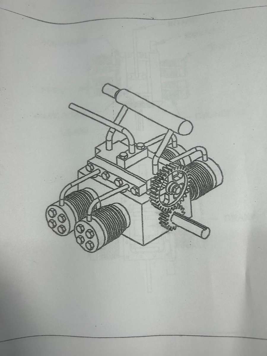
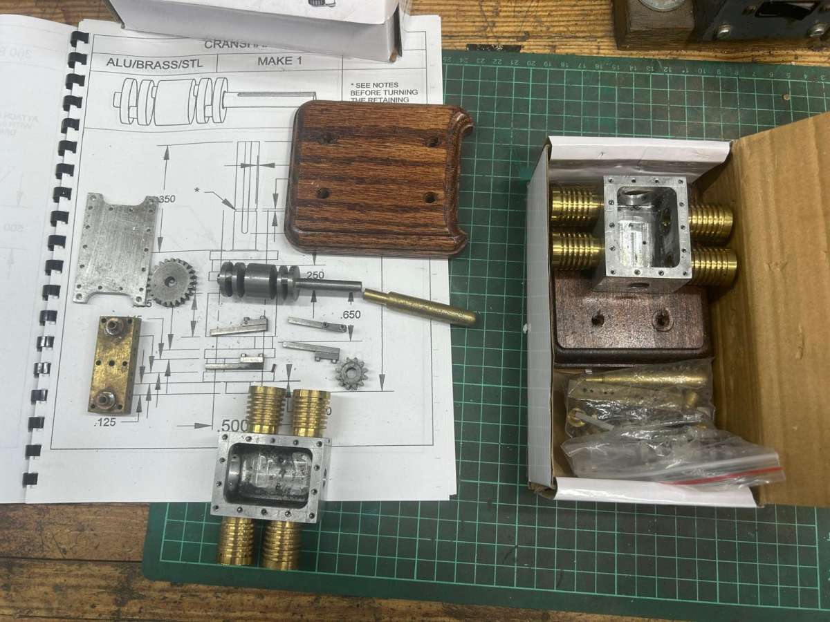


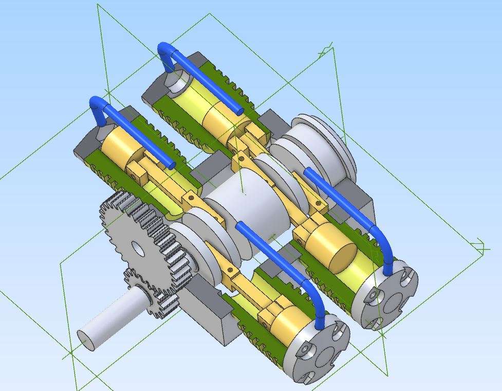
The style of engine reminded me of the Liney "Halo" and after some googling and asking on an American forum it was confirmed that the engine was the Liney RV-2. A flat four boxer air (or steam) engine of 3/8" bore and 1/2" stroke. As soon as the drawings arrived, I redrew them in Alibre to see if all was OK, I just made one change to the pipe positions that come out the central manifold so that they were not offset from the cylinder ctr lines. Apart from that it all looked like it should work. Although imperial the drawings were in decimals and not fractions with many sizes being in multiples of 25, 50 and 100 thou which I have seen a couple of times on other American drawings and quite easy to work with.
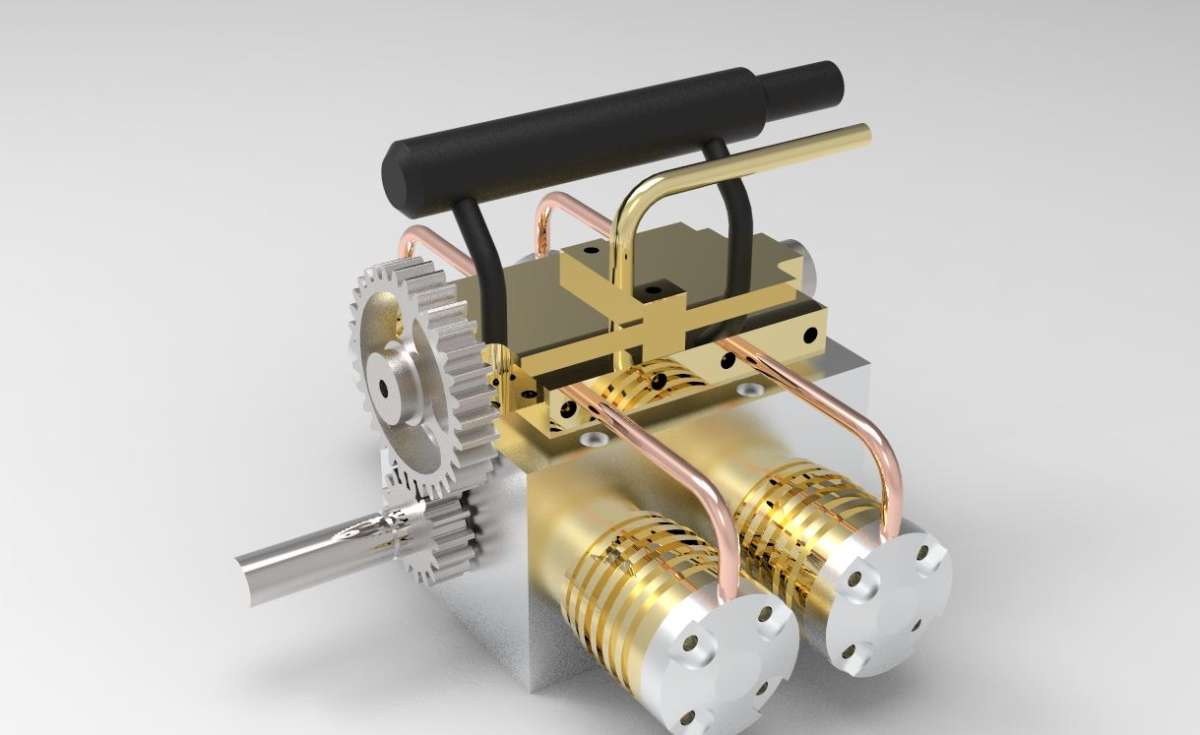


The voyage of discovery started when I took the engine parts down to the workshop. Starting with the cylinders which looked quite nicely machined on the outside it soon turned out that their spigots to locate them in teh crankcase were a bit small and varied bt I can take care of that on final assembly. A bigger problem was the bores which again varied by a thou or two but worse was that they were all tapered and a piece of 3/8" silever steel would only enter so far into each but by different amounts. Luckily I had an expanding reamer to suit that range of sizes so worked my way through all 4 cylinders, slowly increasing the bore until all four were cutting full length. The bore ended up approx 9.75mm.
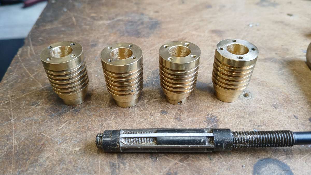


The drawings spec UNC threads throughout the engine mostly #2-56 and #0-80 but I prefer metrix so thought I would be able to rethread the holes for the cylinder head screws M2.5, it was only when I tried a screw in the existing threads that I discovered many were crooked.
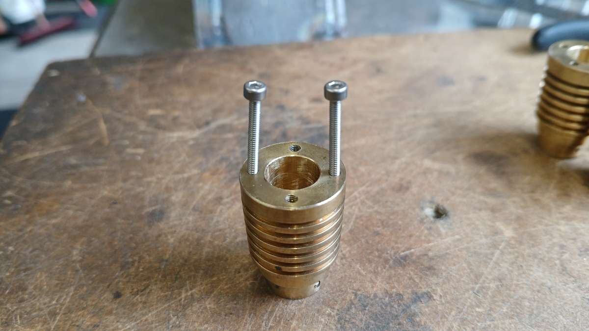


To cure that I decided to drill and tap new holes placed between the old ones and take the opportunity to go down a size to M2
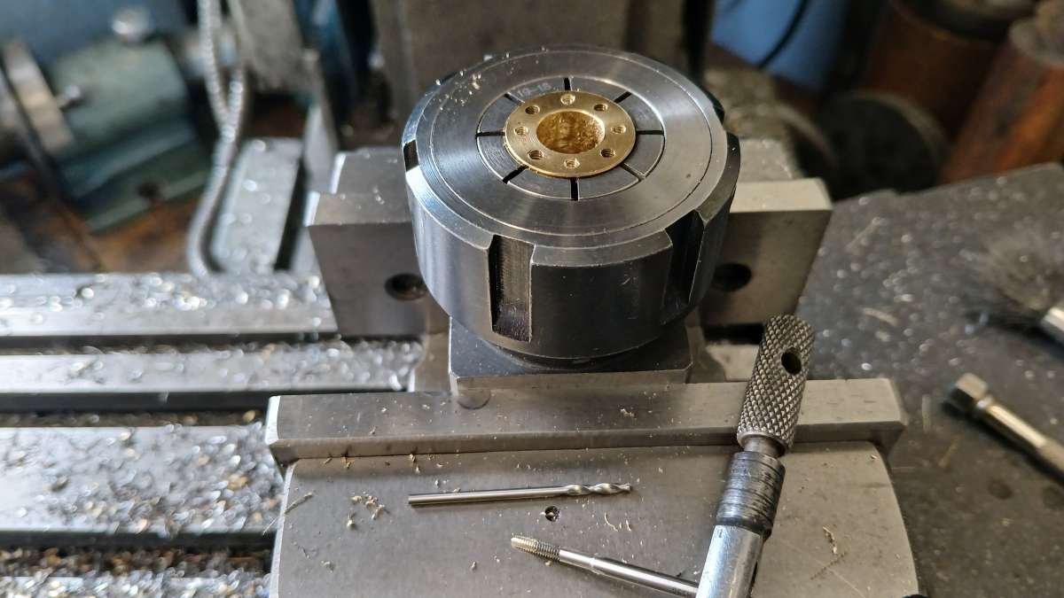


Offering up the sump plate to the crankcase I first thought that the sump was too narrow but after  a quick going over with the digi callipers it turned out that the crankcase was 2 1/16" wide not the 2" called for on the drawings. So after re-tapping all the sump screw holes to metric, it was screwed to the crankcase and the case taken down to width, just skimming the sump at the same time. I then did all the other external faces as the previous builder had polished it up with a buffing wheel, judging by the muck still in the case and it was all a bit rounded over for my liking as well as being too shiny.
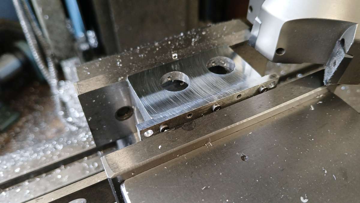


I also got rid of the foot mounting lugs on the sump as I wanted to use the optional rear mount shown in the drawings
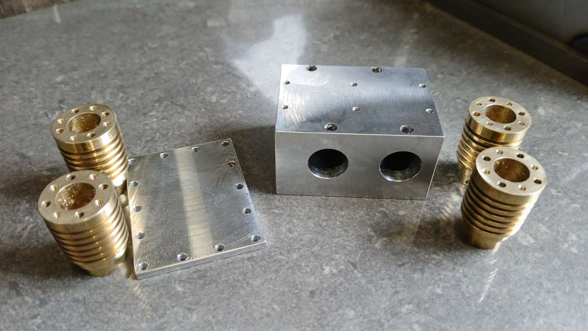


I thought I was done with the crankcase but there were some more surprises to come  :ShakeHead:
redhouseluv
Reply #2 · 6 Oct 2026, 17:28
Looks like a interesting 'gift' and not the 'usual' design for a steam engine. The joys of partially completed engines, maybe be they should be called partially ruined instead :D ::)

Following along  :popcorn: :ThumbsUp:
Jasonb
Reply #3 · 7 Oct 2026, 19:24
Luckily as it is a barstock engines no castings had been harmed by the previous builder which will please Jo.


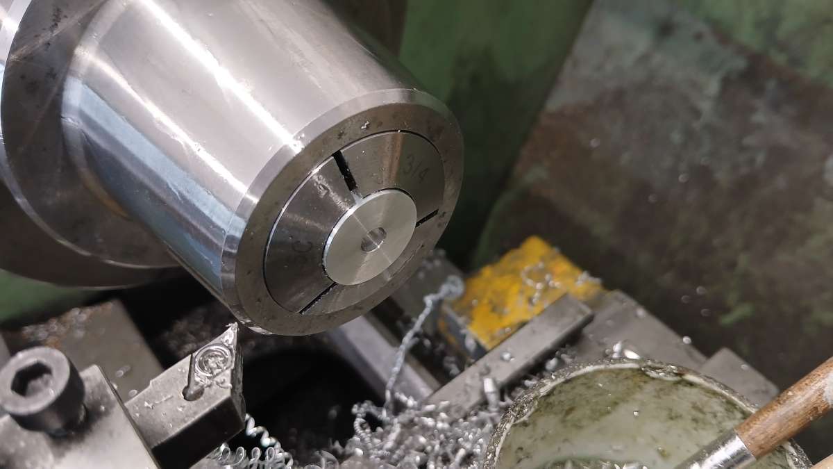
There were no cylinder heads in the box of parts so I made some new ones, opting for aluminium instead of the specified brass. The backstop in a 5C collet made getting them all to the same thickness easy. I reduced the recess in the top of the head down from 3/8" to 5mm as I could see no reason for it to be full diameter which just increases dead space. I also rounded over the top corner.


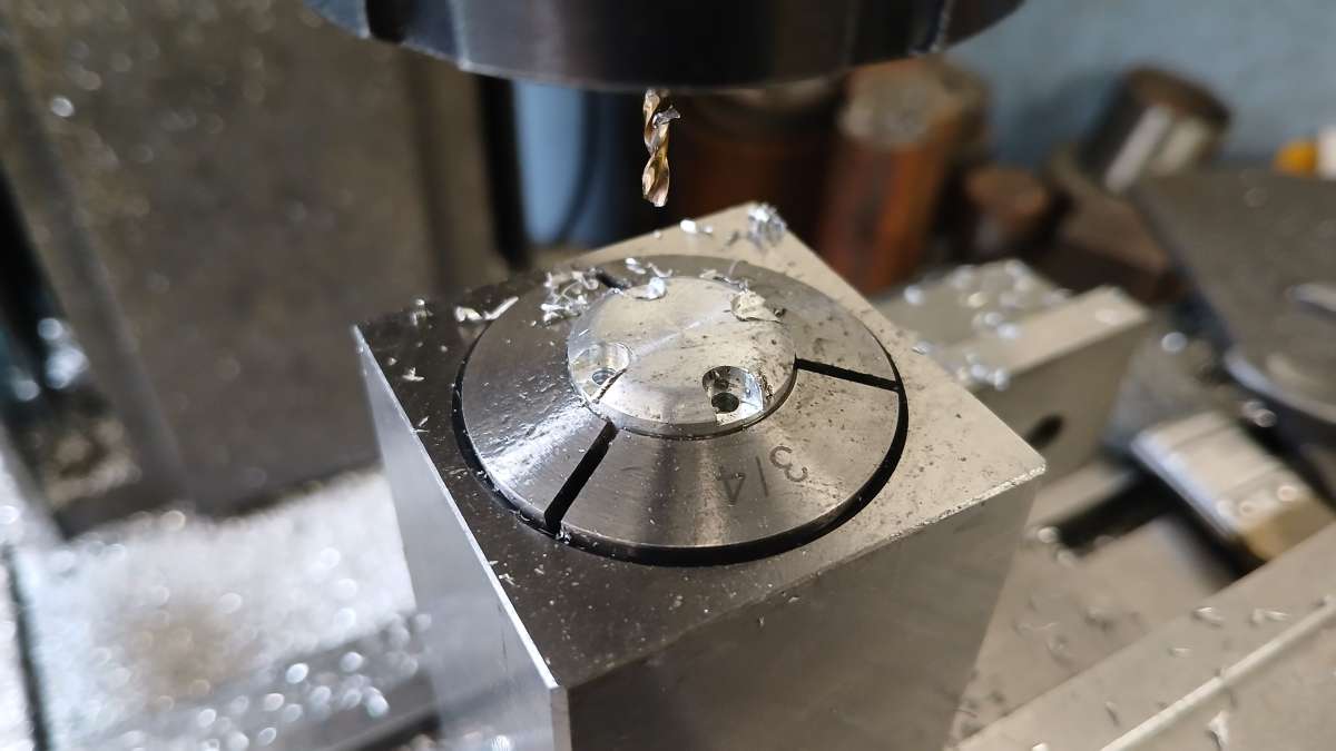
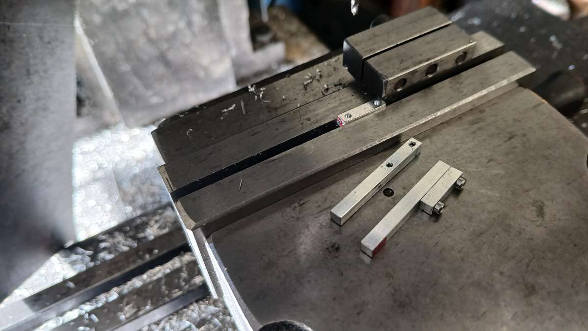
Over to the mill with the 5C collet in a block slots were milled in from the edge to act as counterbores for the cap head screws and clearance holes drilled.


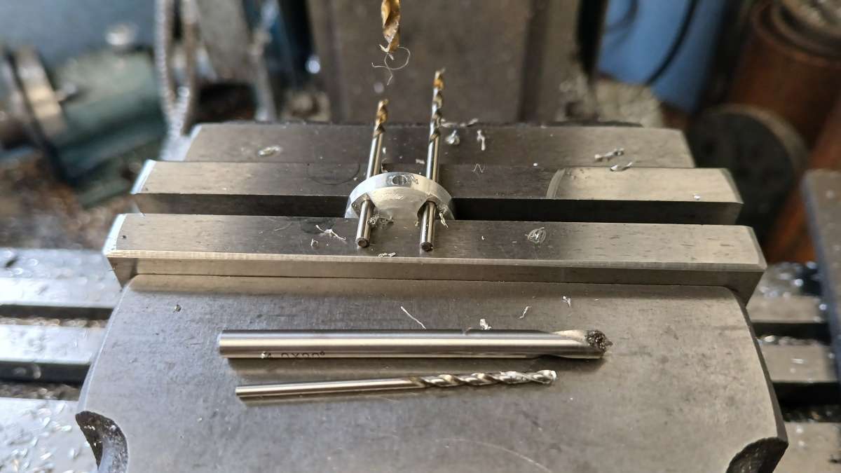
Using a couple of drill bit shanks to align the heads the air passages were drilled and counterbored for the pipes


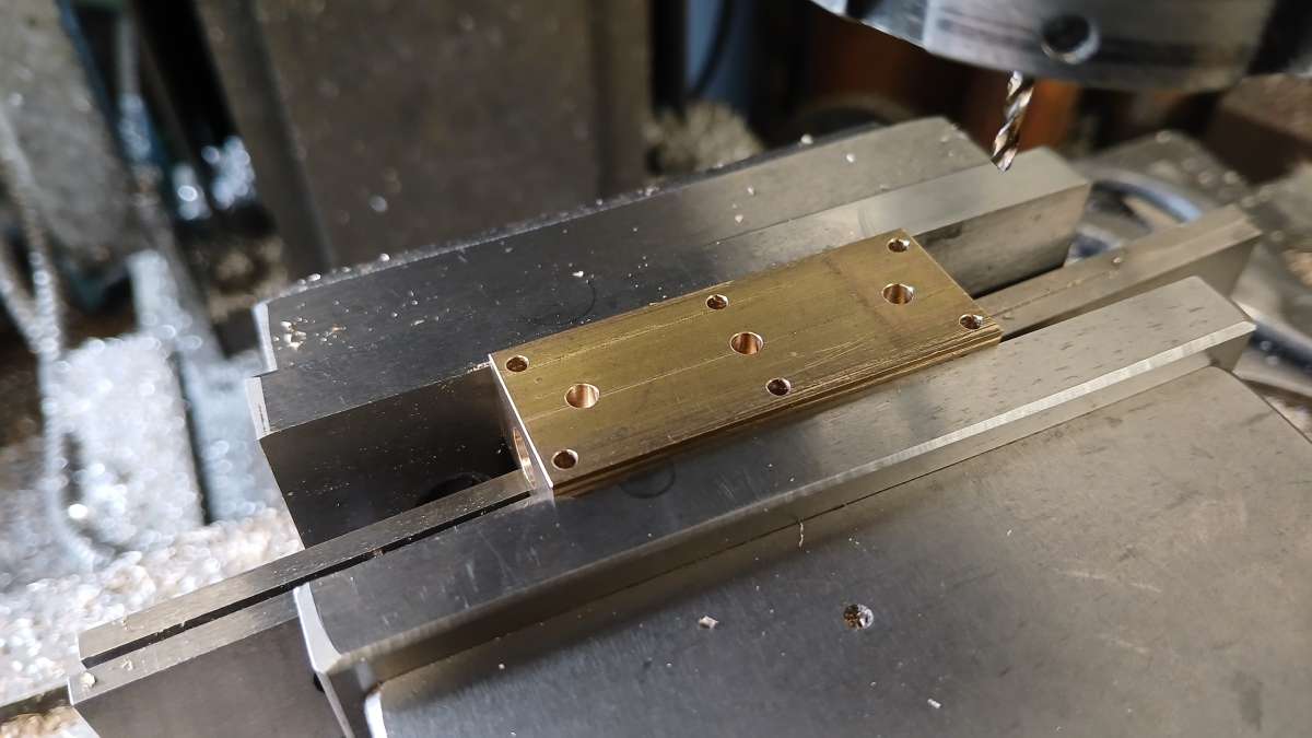
There is a lengthways block of brass that fixes to the top of the crankcase and houses the rotary valve, the hole for which had wandered badly out of position so a new one had to be made. I used 1/2" thick material rather than the suggested 3/8" and left it over thickness so that I could mesh the gears correctly when I got to that stage, or so I thought!

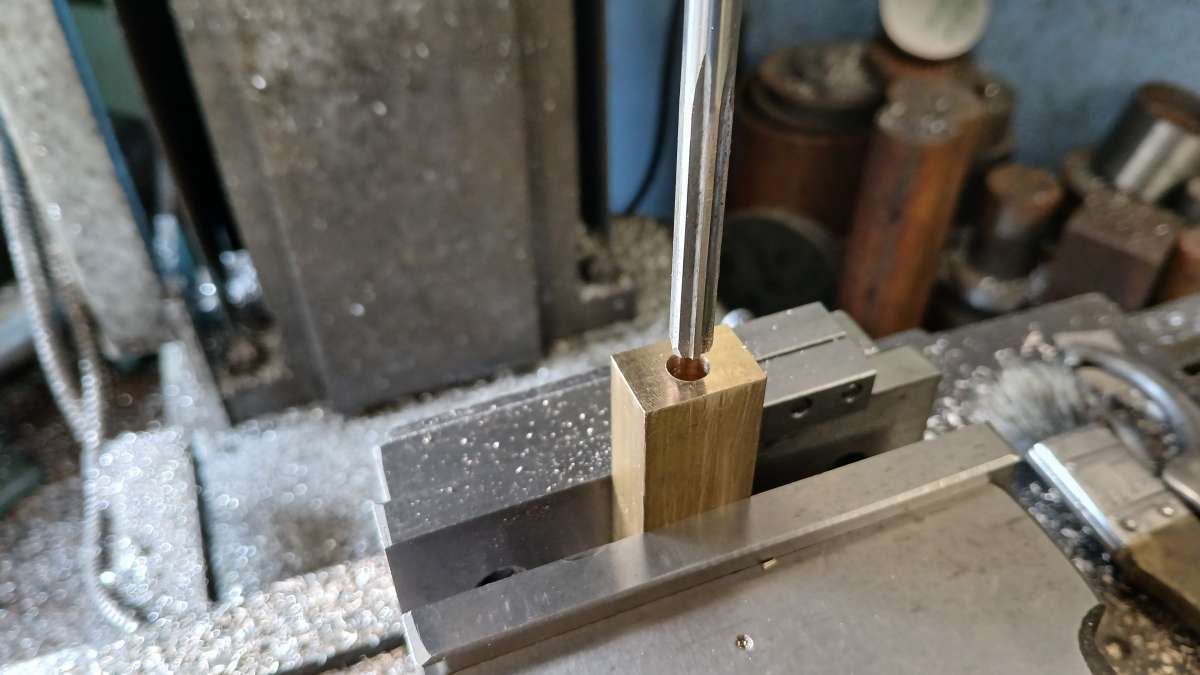
I drilled 6.1mm to approx mid way from each end and then ran a 1/4" machine reamer right through the full 2" length


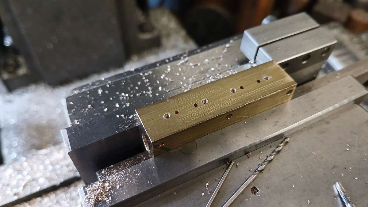
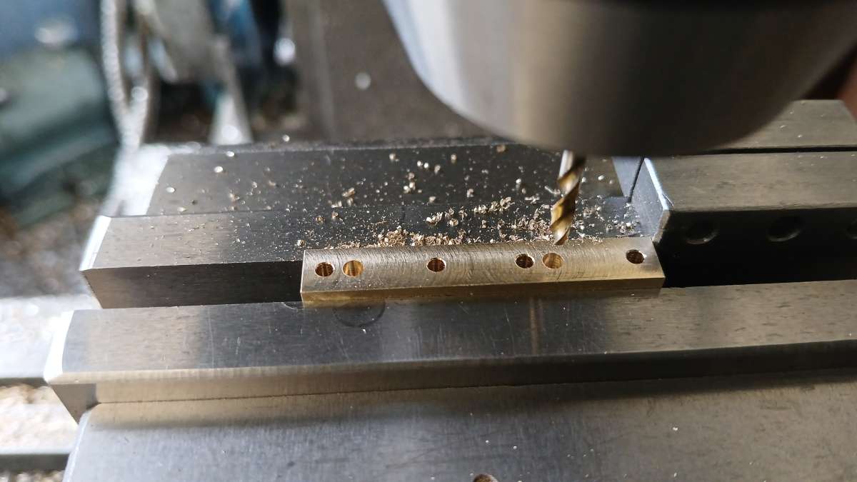
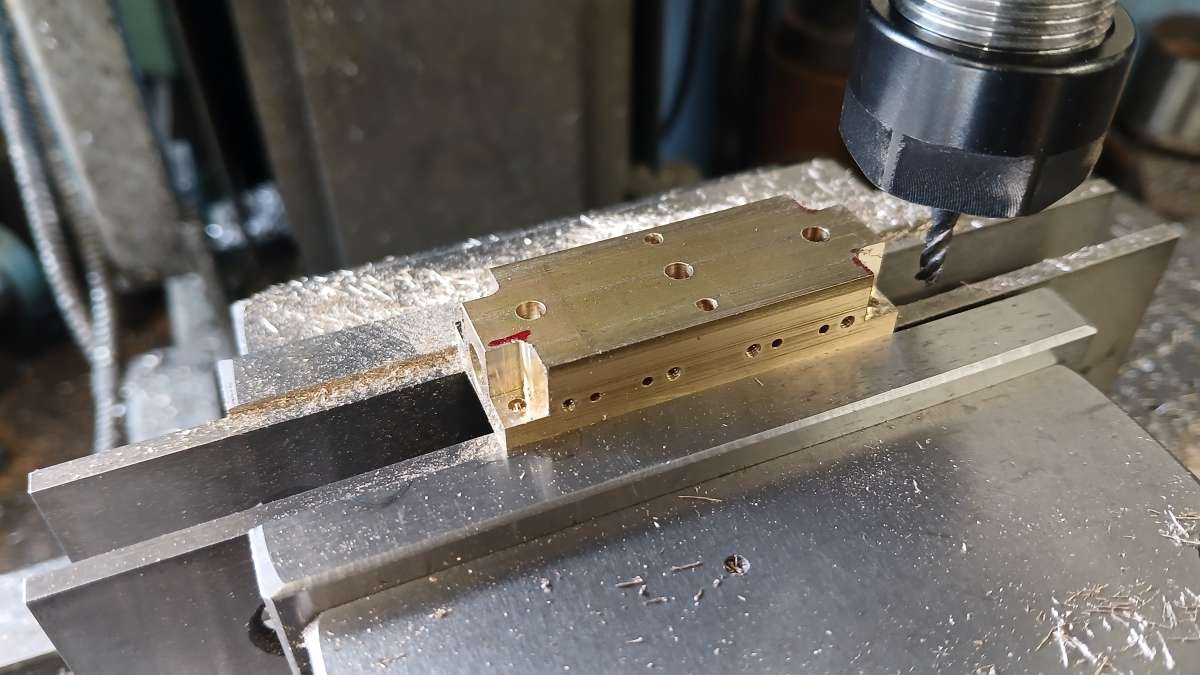
Then added the various holes for air, exhaust and mountings


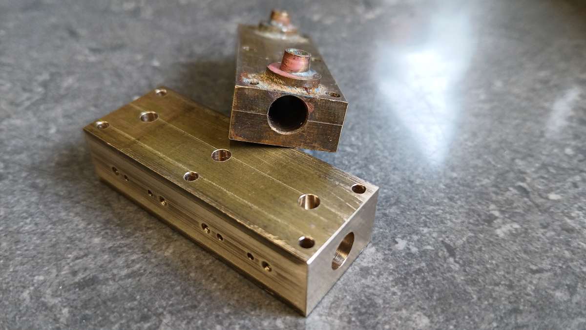
Here you can see how the hole had wandered on the original which would have thrown the gear mesh out ( more of that later) and had also required those ugly bushes to be soldered to the top as there was not enough thickness above the hole to take the exhaust pipes.


The manifolds which run down each side of the valve block were fairly straight forward, I moved the positions of the air pipes so that they lined up with the ctr of each cylinder rather than being off to one side as per the original hole layout.


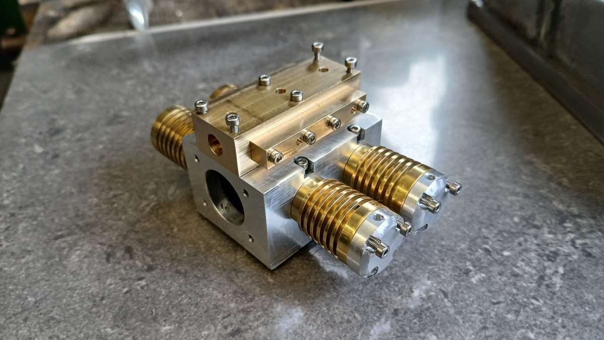
Starting to look a bit like an engine now.

55fairlane
Reply #7 · 8 Oct 2026, 11:12
Quote from: JackPick
Quote from: 55fairlaneFollowing with great interest

Me too!  :popcorn:
[/quote

I saw one this weekendat the IndianaModelEngineShowand now i reallywant to build one]
Jasonb
Reply #8 · 8 Oct 2026, 18:06
Thanks for the interest, plenty more entertaining features still to be found :wallbang:

Crankshaft. All the running surfaces were incredibly rough and would soon have eaten their way through anything running against them. Three of the four crankpins were oversize and one just about onsize depending where you took the measurements as all were tapered. It also looked like the parting tool had wandered sideways as the cut got deeper. But I took on the challenge.

I cleaned up the long shaft and stub shaft so that the flanged ball races would fit and thought I would offer up the shaft into the crankcase to check the various lengths, guess what the hole in the crankcase was too small.

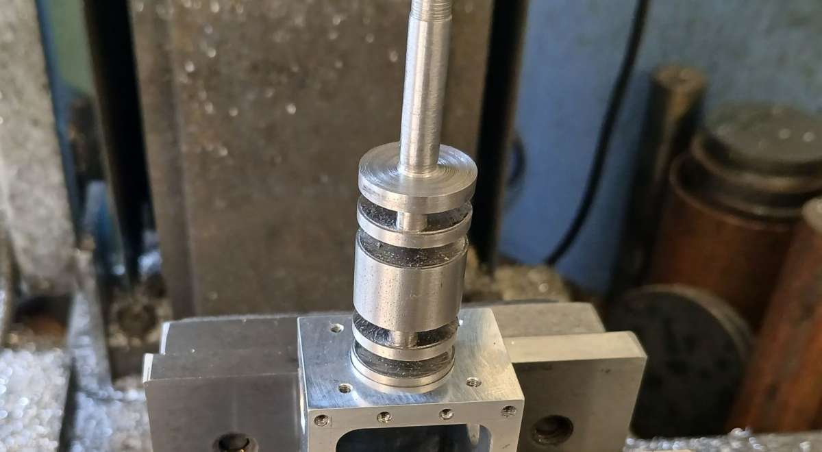
You can see some of the poor machining in this pic where it should drop into the hole


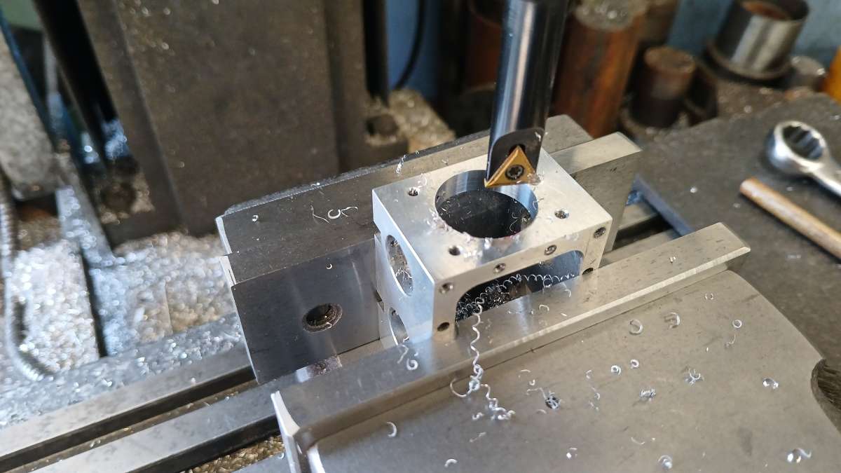
That was soon sorted with the boring head, luckily I had not made the aluminium plug/bearing housing that goes in the hole yet.


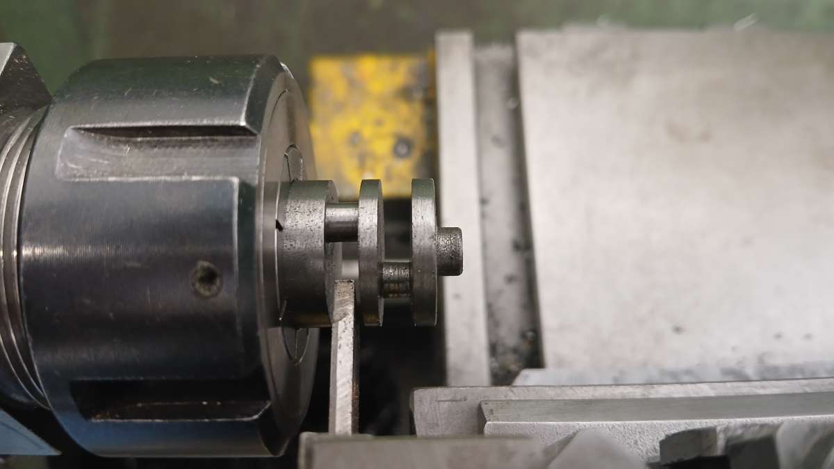
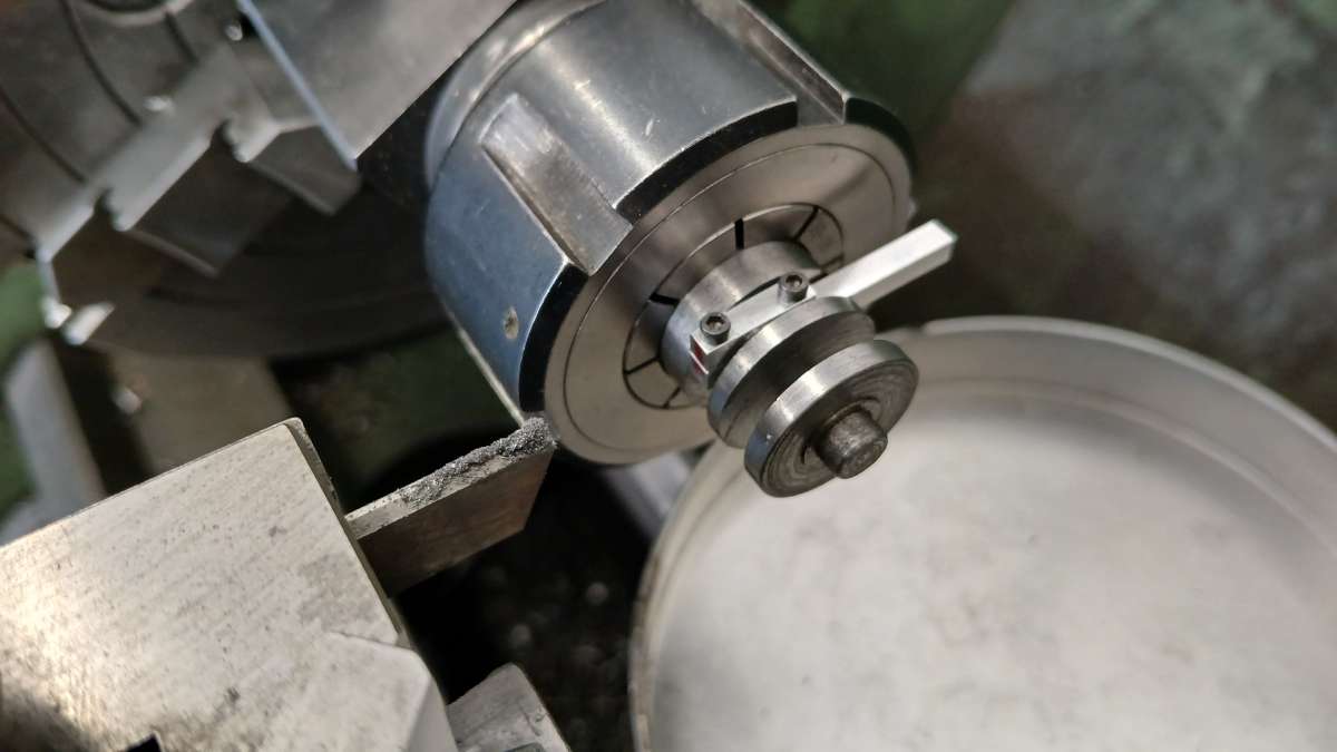
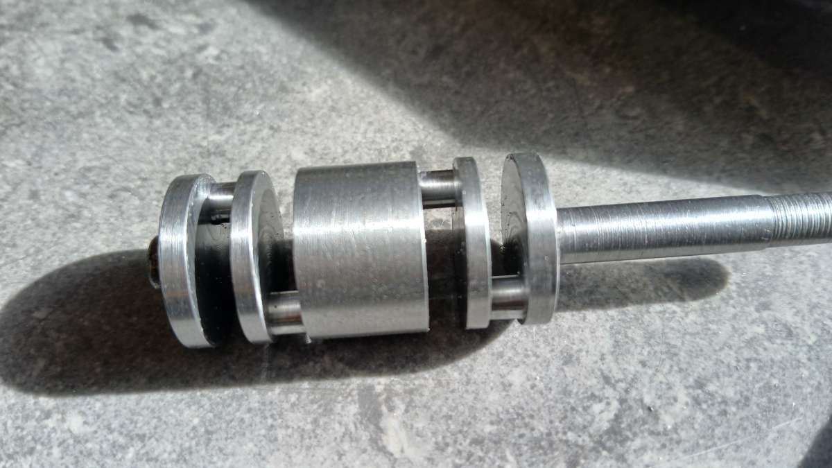
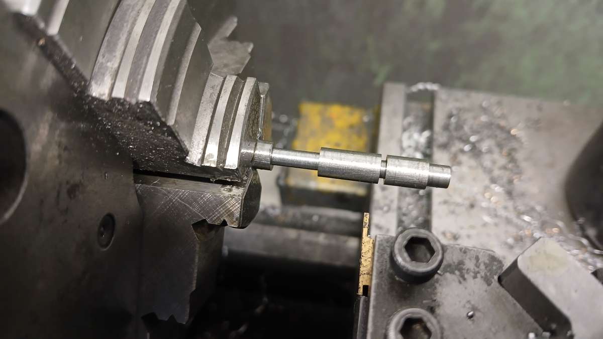
As the gap between webs was only supposed to be 0.140" it was not easy to clock the crank pins into position so I made the job a bit easier by holding a square ER collet block in the 4 jaw and set that with the correct offset. It was then just a case of rotating the crankshaft to position each pin. I used an HSS parting tool as I needed its full flat end width, a GTN-2 insert with it's radiused corners would not have worked. The pin on the left has been finished the other is as it came to me.


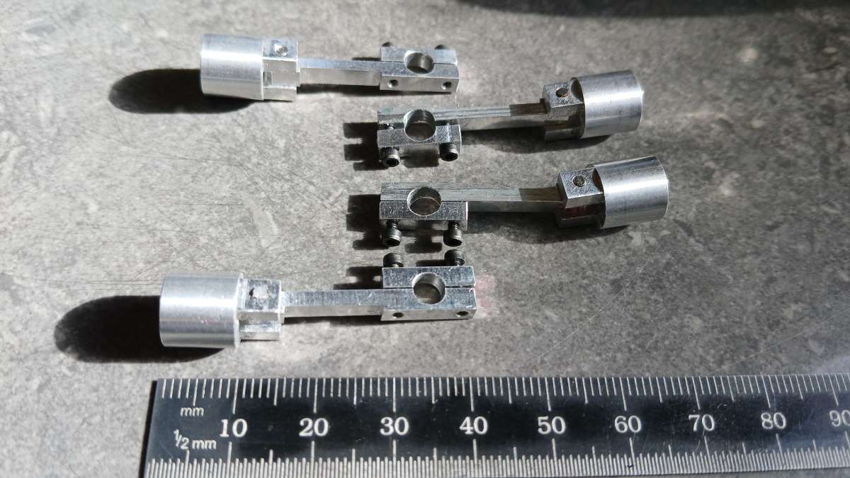
As I could only get in to measure the diameter with the digi callipers I left the crankshaft in the lathe and went over to the mill to make the conrods so the pins could be checked against their reamed holes. There was a set of part built rods in with all the parts but as they had been made from steel (possibly 1/8" sq key steel) is did not fancy running steel on steel. Some offcuts of 2014 aluminium were found and machined to 1/8" square section and then milled to length before drilling and tapping for M1.6 fixings.


Once assembled, three were drilled and reamed 3/16 and used to check the pins. The undersize pin cleaned up to a running fit on a 4.4mm drilled hole. They were machined so the assembled rod would rotate with light finger pressure but not drop with it's own weight. Then a quick "shoeshine" with a thin strip of well worn 240g Emery cloth against the rotating pin just polished the surface and allowed the rod to drop. The metal dish below it to save loosing anything in teh swarf tray as the big end caps are only 1/2" long.


With that and the bearing carrier done I did need to reduce the overall length slightly so the shaft would spin freely between the flanged bearings without any noticeable end play. There is still an e-clip groove and keyway to be added to the long end.


I could not resist adding all the conrods and giving the crankshaft a spin. The shafts were a bit too close to the top of the crankcase for comfort so I decide to take an additional 25thou cut to make sure nothing was hitting. More of that story revealed itself later  :facepalm:
Chipswitheverything
Reply #10 · 9 Oct 2026, 07:54
Amother interesting build log, good job that the engine came to another builder who had your expertise..    There is an annoying tendency to call second hand items "pre-loved", maybe in model engineering we should adopt another term, "pre-wrecked"  !
Jasonb
Reply #11 · 9 Oct 2026, 18:59
Next I decided to make the rotary valve, this is specified as silver steel but I though stainless would be better and it was actually a slightly closer fit in the reamed hole. First job was to reduce the end to fit the gear, I had already spotted that the hole in the gear was larger than the specified 3/16" and by the looks of it the previous builder got as far as drilling about 15/64 and realised his mistake and did not go as far as reaming 1/4 which would just have slid along the 1/4" shaft.

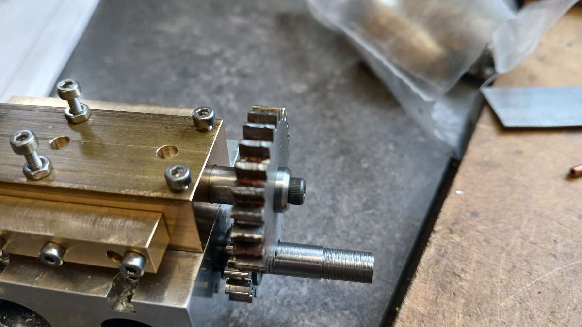
With the gear on it's slightly reduced spigot and retained by the "washer" detailed in the drawngs I offered it up to the part assembled engine. Now as I had left some metal on the bottom of the valve block things should have gone together with a lot of backlash in the gears but as you can see they would not mesh as the ctr distance was too small.


It was at this stage I realise dthe crankshaft hole had been placed far too near the top of the crankcase and that would also have explained why I felt the conrods were getting too close to the inside top surface. My options were to either make a new crankcase or something else. In the end I opted for something else in the way of some new gears, this was partly decided by the poor finish on the larger gear, if you look at the crests of the teeth in the photo above you can see how uneven they are along their length so may not have run well even with the correct PCD

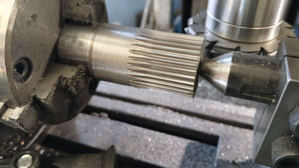
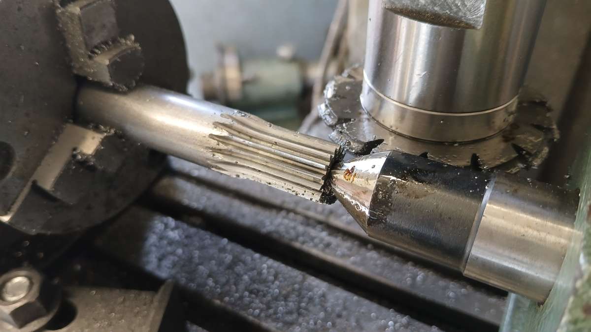
By reducing the gears from the original 30DP down to 32DP I could get them in with just a little to come off the bottom of the valve block as originally intended. The large one was cut from cast iron bar and I cut the stick long enough for two.


The same for the smaller one which was cut from steel


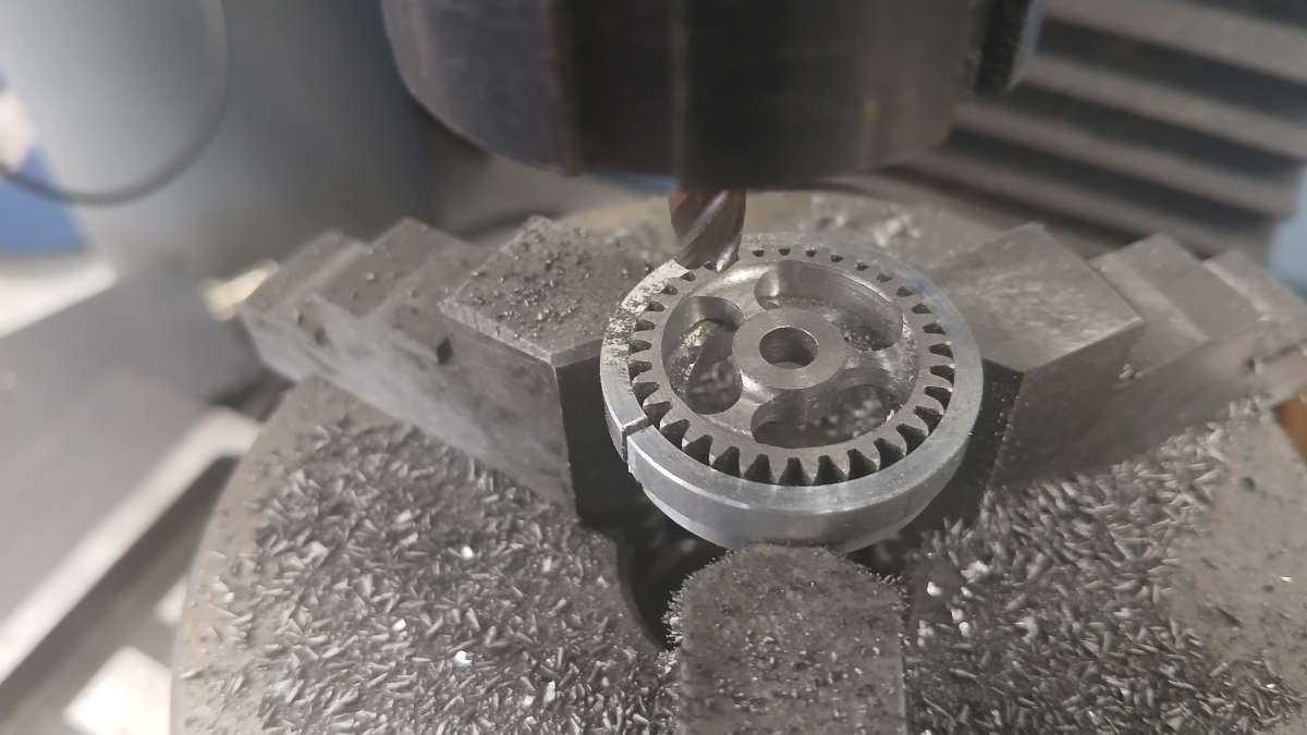
A few minutes on the rotary table had the large gear looking a bit more interesting. The central hole was the correct 3/16" this time.


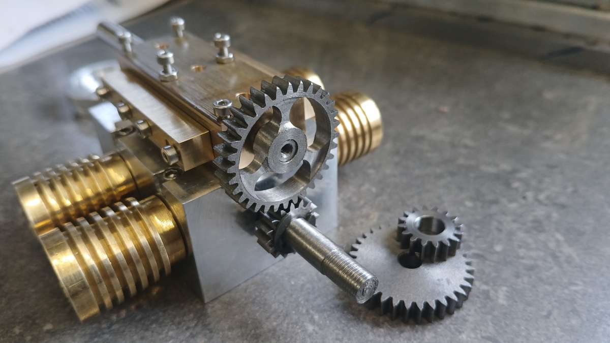
And they went together, still the material to come of the valve block which is why the gap is large
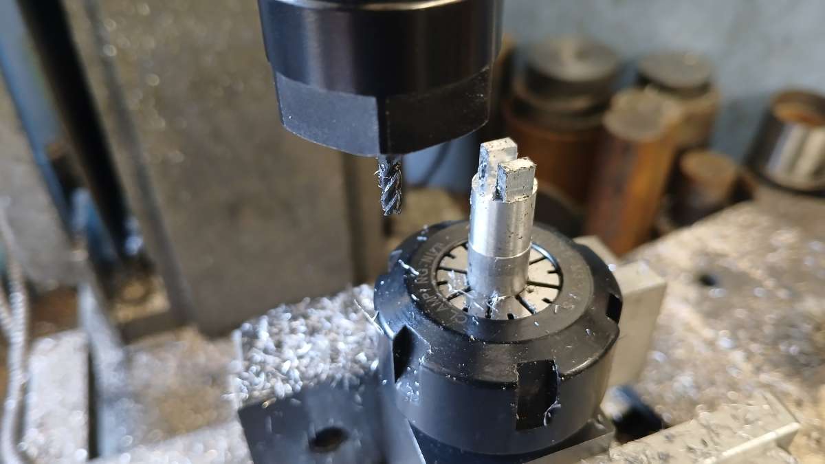


I could now get on with the valve, just a case of cutting the groove nearest the end, moving the bar out of the chuck a bit more and doing the next groove.


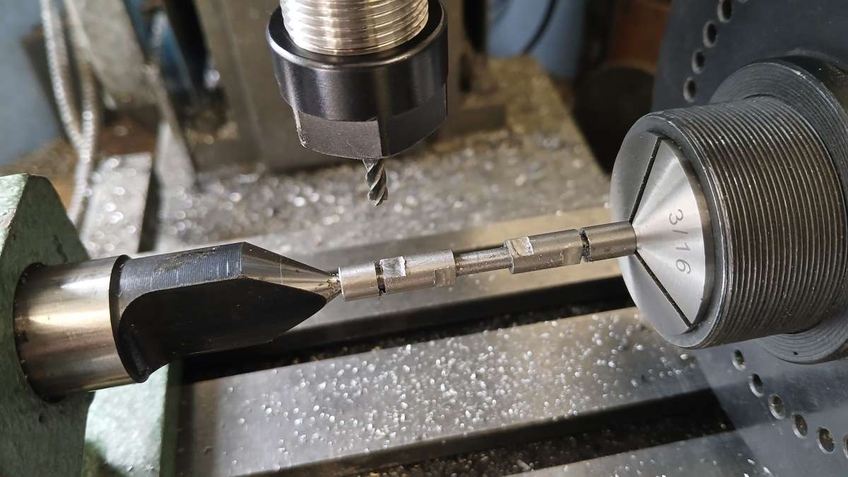
I used the 5C spin indexer to position the cuts at 90deg as I can get in closer than a chuck on the rotary table allows. The flats are what open the various drillings and passages to allow the air in or out.


With the valve block milled to final height the pockets could be milled in each corner to clear the screw heads.

redhouseluv
Reply #12 · 9 Oct 2026, 19:29
Very impressive, the dark art of gear cutting, where beginners fear to tread, or is it just me?  ;D

I like the idea of keeping the spacing the same and changing the gears to accomodate. The old set look well worn even though they've probably never been run! :popcorn: :ThumbsUp:
Jasonb
Reply #13 · 11 Oct 2026, 17:44
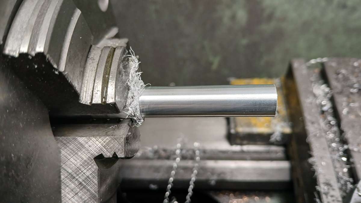
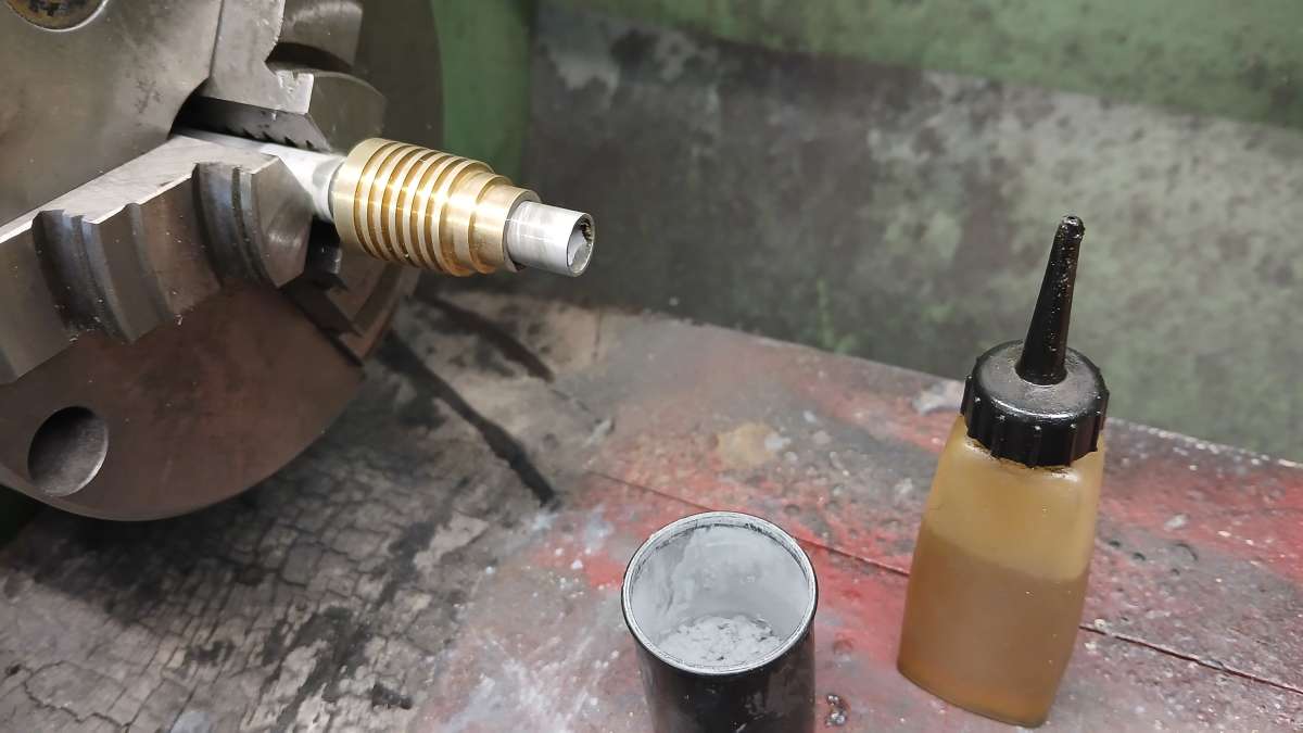
Before making the pistons, I thought it best to lap the cylinders so an odd bit of 10mm dia aluminium tube was turned down to a close fit inside the now all the same size cylinders. That is the paint layer at the chuck end not swarf.


Some 1000grit silicon carbide powder mixed with a little oil made a suitable paste to give each cylinder a quick lap.


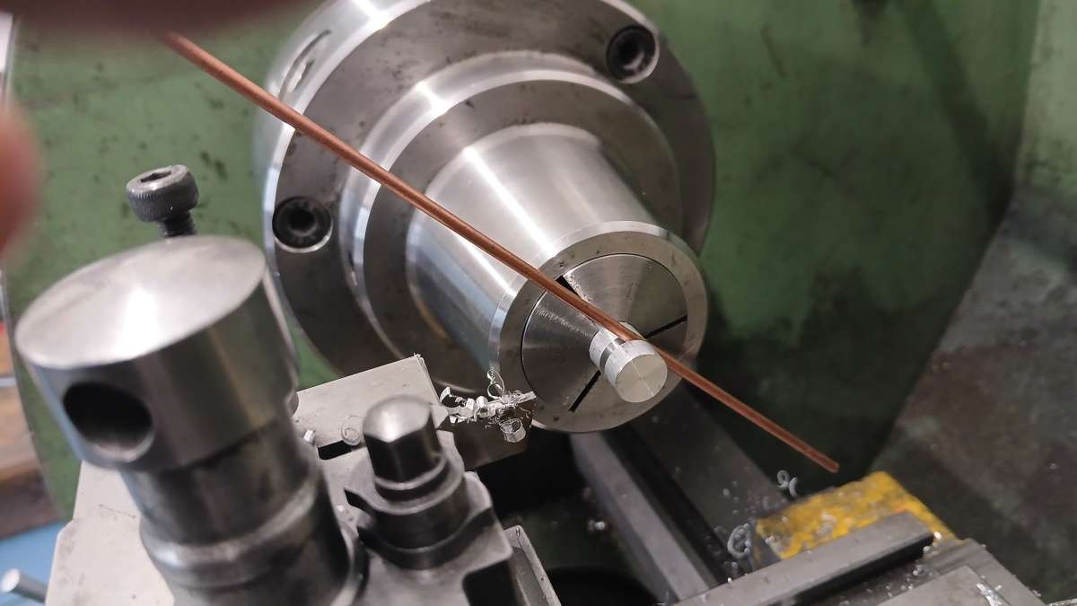
It was then just a case of turning some 10mm aluminium down to size for the pistons using the cylinder as a gauge to get the correct fit. These little pistons have a forked end machined at the bottom to take the conrod.


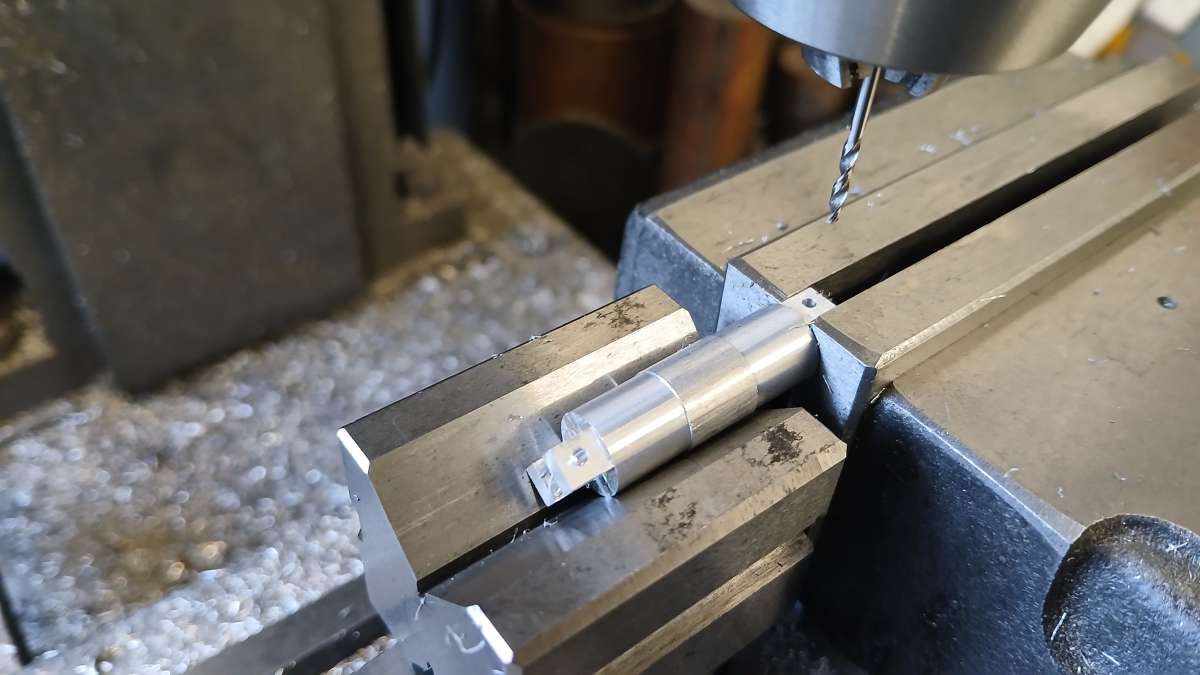
Which is then cross drilled for a 1/16" gudgeon pin


I found that 1/16" iron rivits were a good fit as the shank just below the head increased in diameter so with the addition of a tiny drop of Loctite they could be pushed firmly home and the excess sawn off with a piecing saw.


It was hard to resist a quick trial assembly to check if things went round and round or in and out as they should.

https://youtu.be/jBRyAc3IAq8?si=WrWXt2jvj2MaG8BGYouTube video

About now the last of the gifts from this set of parts that kept on giving made itself known. Turns out that matey boy who started the build got his crank pins in the wrong positions so instead of having two pistons on the power stroke and the other two on the exhaust stroke all four moved in unison😬😬😬😬

There was no other way around it other than to make a new crankshaft, I guess I should have checked the old one more closely before doing the remedial work on it but where is the fun in that. Having the crank webs as full circles makes it quite easy to hold and it is just a case of turning one pin, sliding the material out a bit more and turning the next.

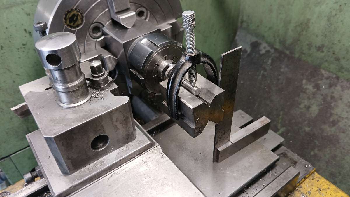
Luckily I had left the ER collet block in the 4 Jaw so there was not much to set up. After doing one pin I used a square to set the collet block's edge vertical and then clamped a vee block to the shaft checking that it too was vertical. Then simply rotate the shaft and it's vee block 180 degrees and it was ready to cut the next pin.


https://youtu.be/vNxVZ93Xd38?si=emeFo55In42AOyOyYouTube video

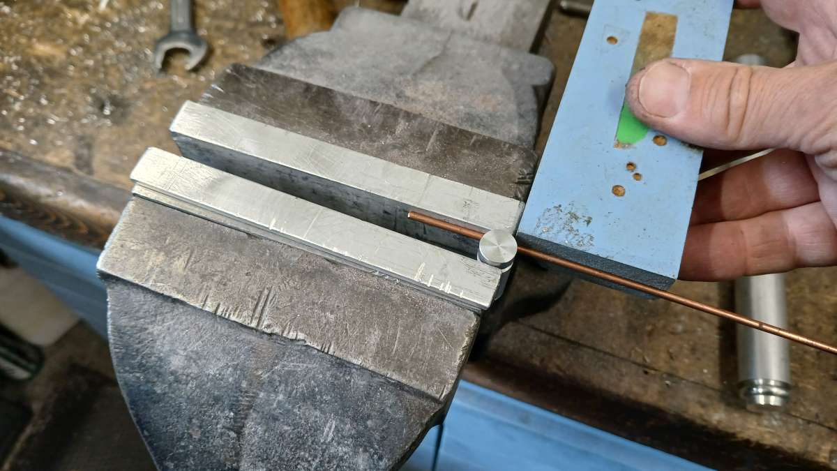
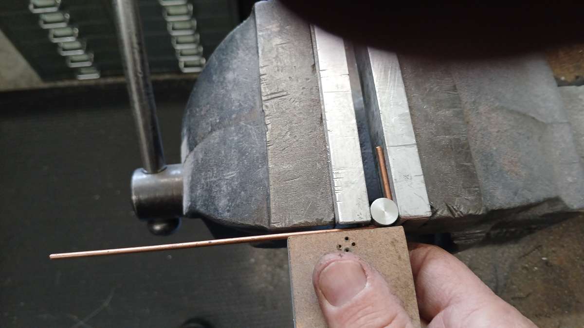
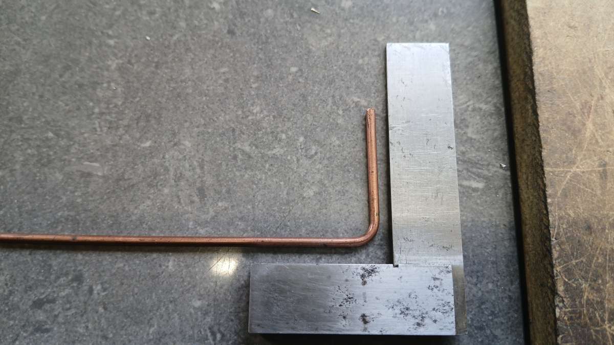
As you know I'm not one for tool making so no fancy pipe benders for me. Just a groove cut in the end of a bit of bar the width and depth of the tube to be bent.


Then hold the two in a vice towards one end and push the pipe round with a bit of something flat, MDF in this case


Rinse and repeat for the other pipes needed


That gave me enough parts to see if the thing ran or whether there were any more hidden features that I had not spotted. I did not run it too fast as the prop is only pushed on for now.

https://youtu.be/TY8ugz56_E0?si=9qNKy1Jj04ceVLVxYouTube video
redhouseluv
Reply #14 · 11 Oct 2026, 18:38
That is so cool, what a 'challenge' to get that to run! I've not seen a similar looking engine with 4 opposed cylinders, it's a great design even if the original builder had made a 'few' errors along the way!  :) Out of interest were the errors all build errors or were there any in the drawings themselves?

I'd have never thought of putting a collect block in the 4 jaw to create an offset to make a crank, will have to remember that one.

Nice work, on a minature scale, really well executed  ....... as usual!  :popcorn: :ThumbsUp:

Quick reply

Log in to reply.