No errors on the drawings, just a couple of bits I felt could be improved on which I did.
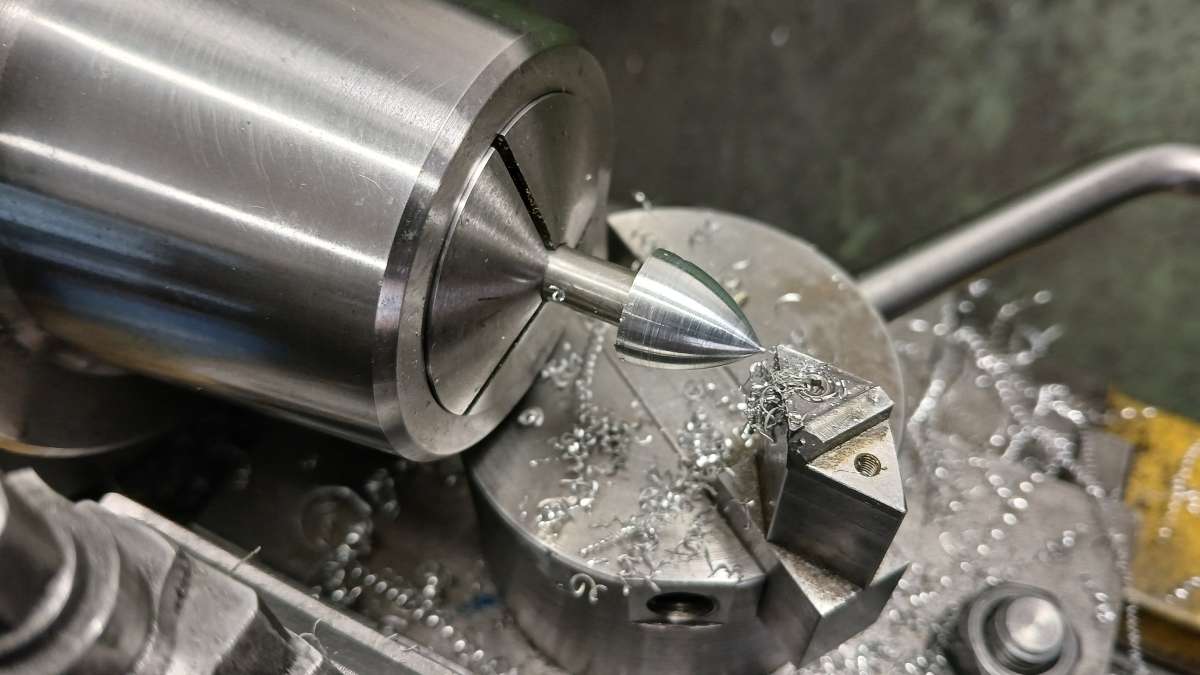
With a running engine the last few bits could now be done to make it look nice. First was a prop spinner that was shaped using my ball turner. I also had to add a small spacer between the prop and crank gear to ensure that the blades cleared the head of the screw that retains the larger valve gear.
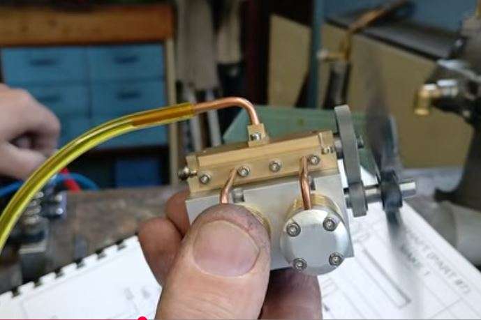
You can also see in this still from the video that I have added spacers to keep the gears clear of the cranckcase and valve block, there was nothing in the original design to stop the gears rubbing on things. You can also see that by moving the hole positions from centrally between the pairs of screws to close to the right I have got a straight pipe run from manifold to cylinder
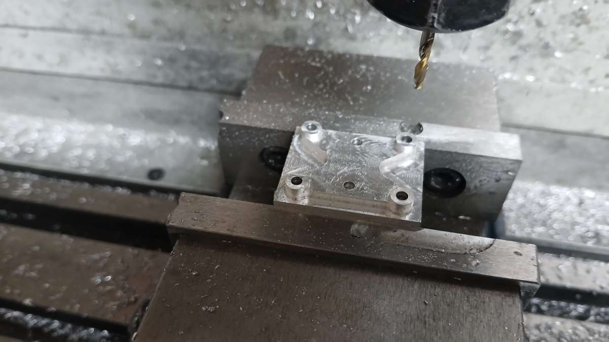
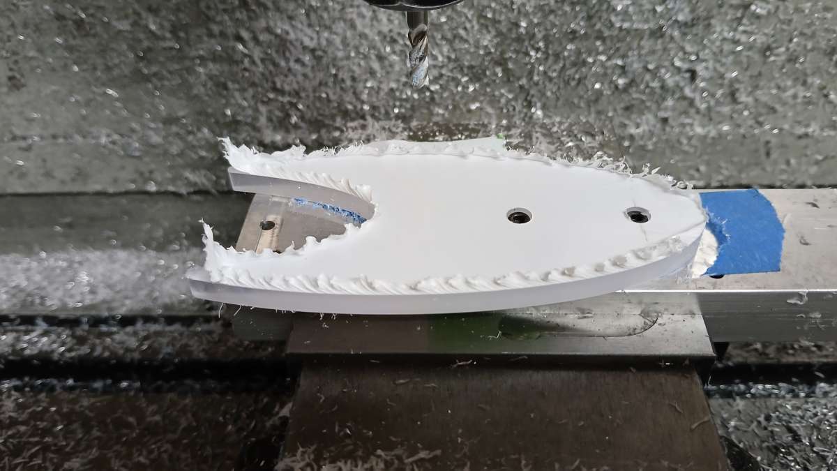
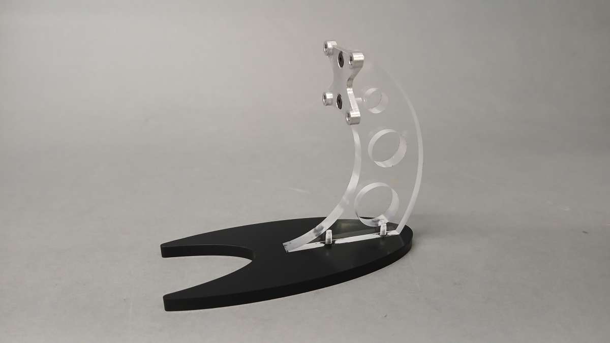
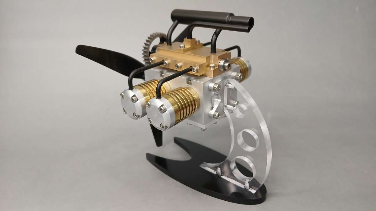
The drawings show hole positions in the crankcase for rear mounting of the engine but no details of a stand, so I made one up. The rear bearing carrier has a press fit specified but I did not want to do that as getting it out would mean pressing on the end of the crankshaft which could bend it. So I went with a push fit (actually held in the video above) and designed the stand bracket to ensure that the bearing carrier could not come out. It was shaped on the CNC
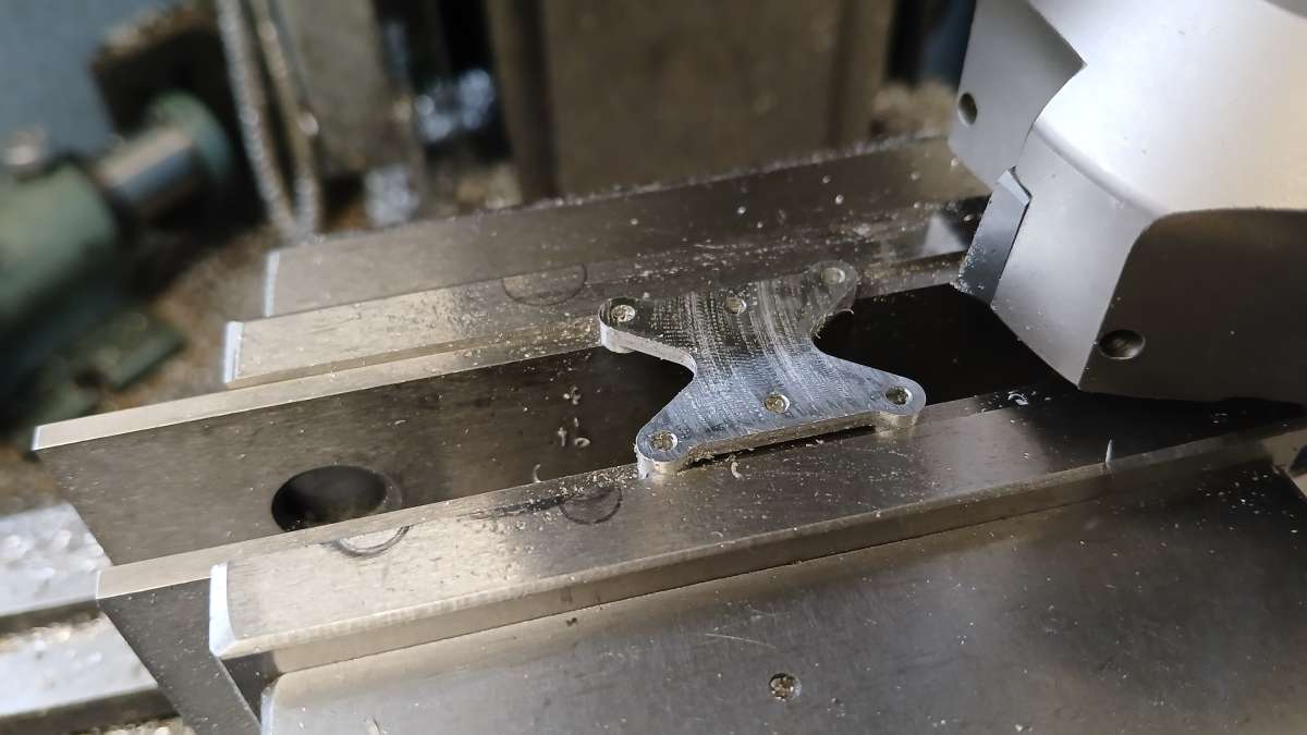
And then the excess material used to hold it by decked off on the manual mill
The remaining parts were CNC cut from scraps of acrylic sheet
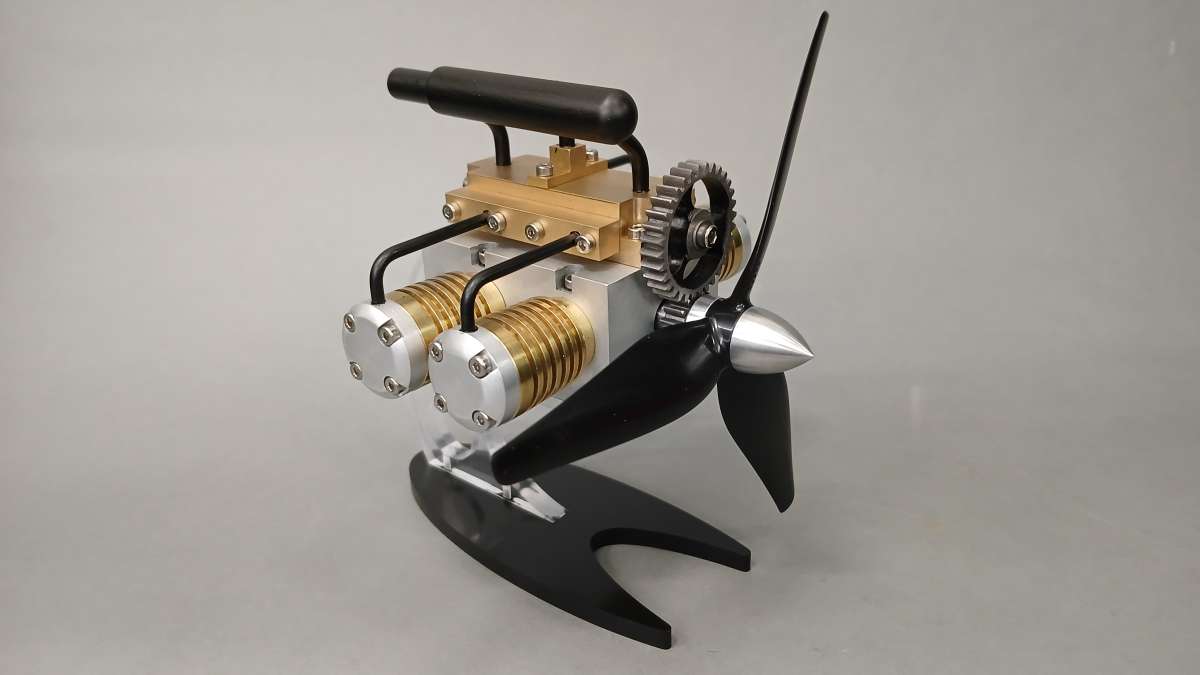
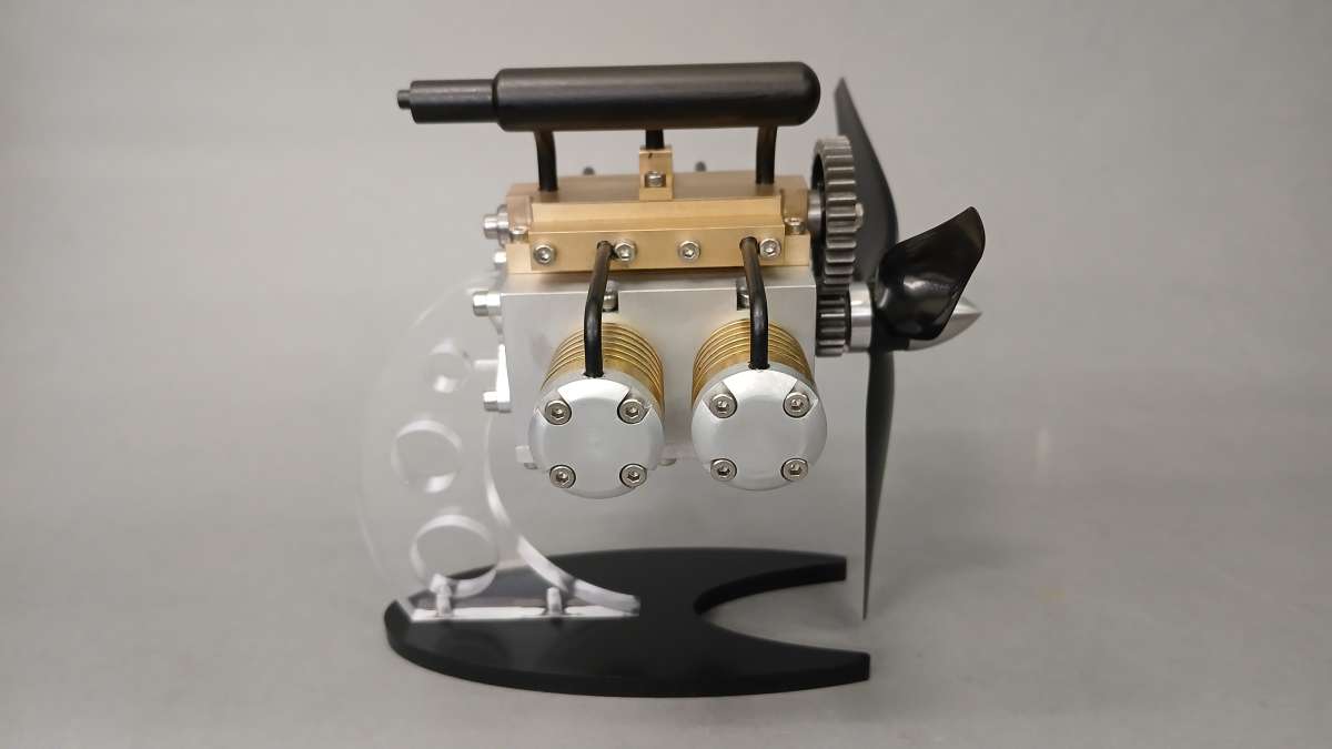
The exhaust "silencer" was the only part that did not have any errors, I added the missing pair of pipes and that was it. I think it actually sounds better with the silencer fitted. The prop is a spare part for a drone and most of the bare metal has been bead blasted.
 https://youtu.be/RYdZqtwKNSE?si=B-4ofIb6X_3-yYit









