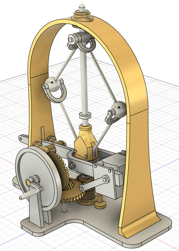
As with the patent model, it will be driven by a hand crank to demonstrate how it works. This style governor used much lighter flyballs than most other designs, and ran at a higher speed, and used a sliding counterweight on the output lever to make it more responsive. They were produced and used on engines, so it was not just a patent idea. I'll be making mine with 1" flyballs and the hoop is about 8 inches across.
I got the hoop made yesterday and this morning. The original design had a hoop with a wider base/narrower top, but I had a couple lengths of flat brass bar 1" wide and rounded on one side - it was made for use as the stem band on a boat, one of my cousins had some left over and gave it to me years ago. After cleaning off the layers of dust from sitting out in the garage for years, I took a look at rolling the bend into it, but my slip roll is too small/light to form this bar, which is about 1/4" thick in the center. So, I annealed the center with a torch, let it cool, and hand formed it over a piece of pipe. The pipe was several inches smaller than the bend needed, so it was done by eye, with a couple rounds of adjusting in the vise to get an even curve the right diameter.
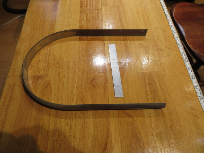
After sanding off all the tarnish with a 1/4 sheet palm sander, it was given a spray of clear enamel to protect the finish. Looks much nicer after the cleanup!
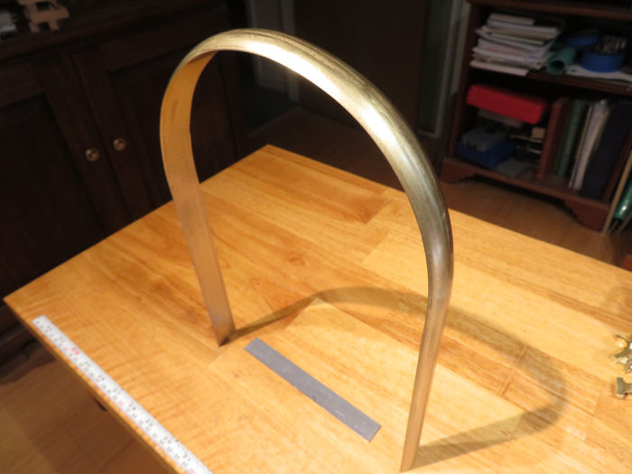
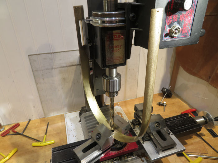
Then I needed to drill the mounting holes for the base, the swivels, and cut a slot for the lever arm. Doing all this before rolling it would have been very difficult, getting the holes to end up in the right places would have been a nightmare. So, with it shaped, I set up on the mil the drill the mounting holes. The other leg of the hoop just clears the top of the headstock. If it did not, I could have put the other leg below the table, but it was easier to drill into the flat side.
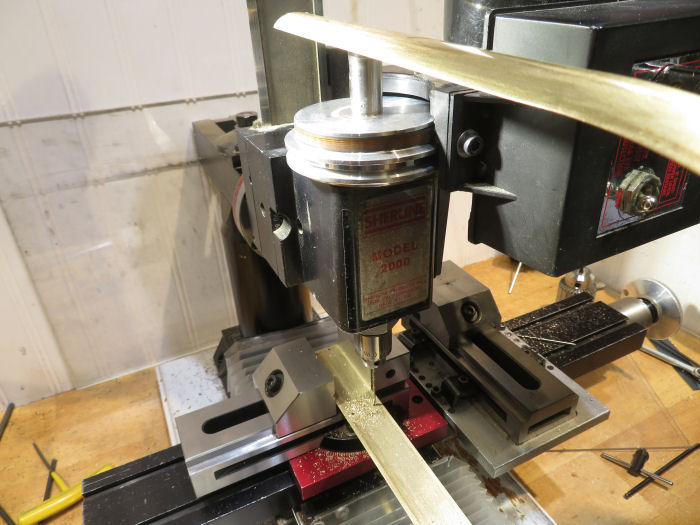
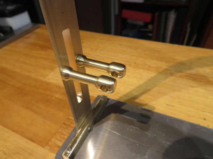
Also milled the slot for the lever arm, which gets moved up and down as the flyballs move in and out - the end of this arm would be connected to the steam or cutoff valves, depending on the engine.
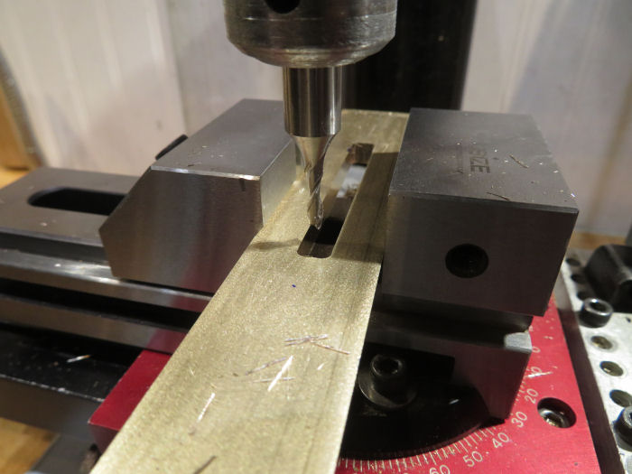
There is a large hole at the top of the hoop to hold the top of the center pivot rod. I marked the location with the hoop standing on the table, and set it up to drill on the mill. The vise needed to be turned to let the legs clear the headstock, they would not quite span the motor when lined up with the table. A bearing will go in this hole.
Final step this morning was to make the crossbars to bolt the hoop to the base plate. The top corners are rounded off around the hoop, though thats hard to see in this picture.
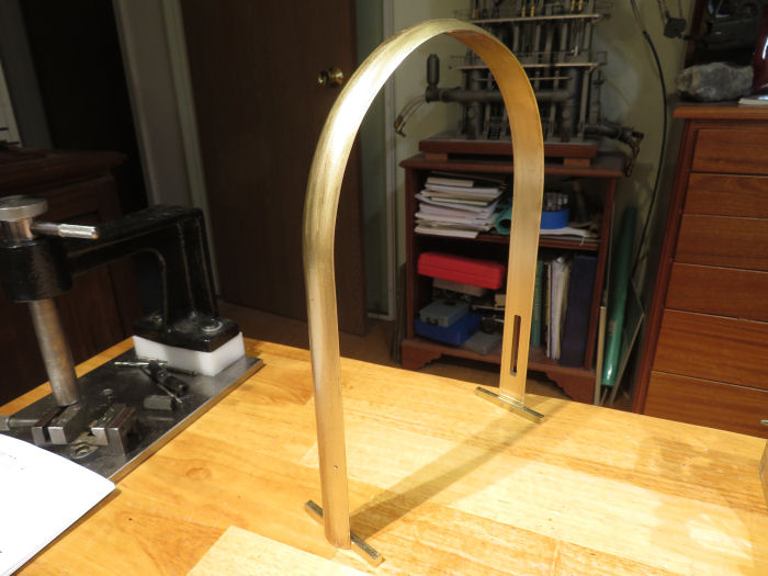
Next up will be to make the base plate. Probably will use some aluminum sheet stock for that.
And yes, the Diesbar engine is still on the bench, having fun running that on the side...


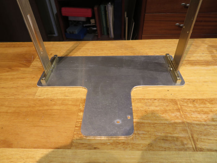
 Not a problem, I plugged the bad holes with some brass screws, and drilled/tapped new ones in the proper place.