Thank you Zephyrin, I can only hope it is not above my level!
Hi Mike,
It's not just the drawings and photos that are valuable, but the text materials also. I wondered about the arrangement of the knife and fork connecting rods; do all the knives go up one bank and all the forks the other, or do they alternate? The Wolsely manual gave the answer - viewed from the rear, the knives get the left bank, the forks the right.
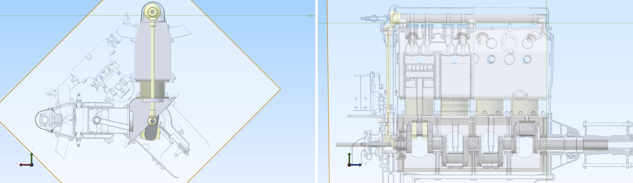
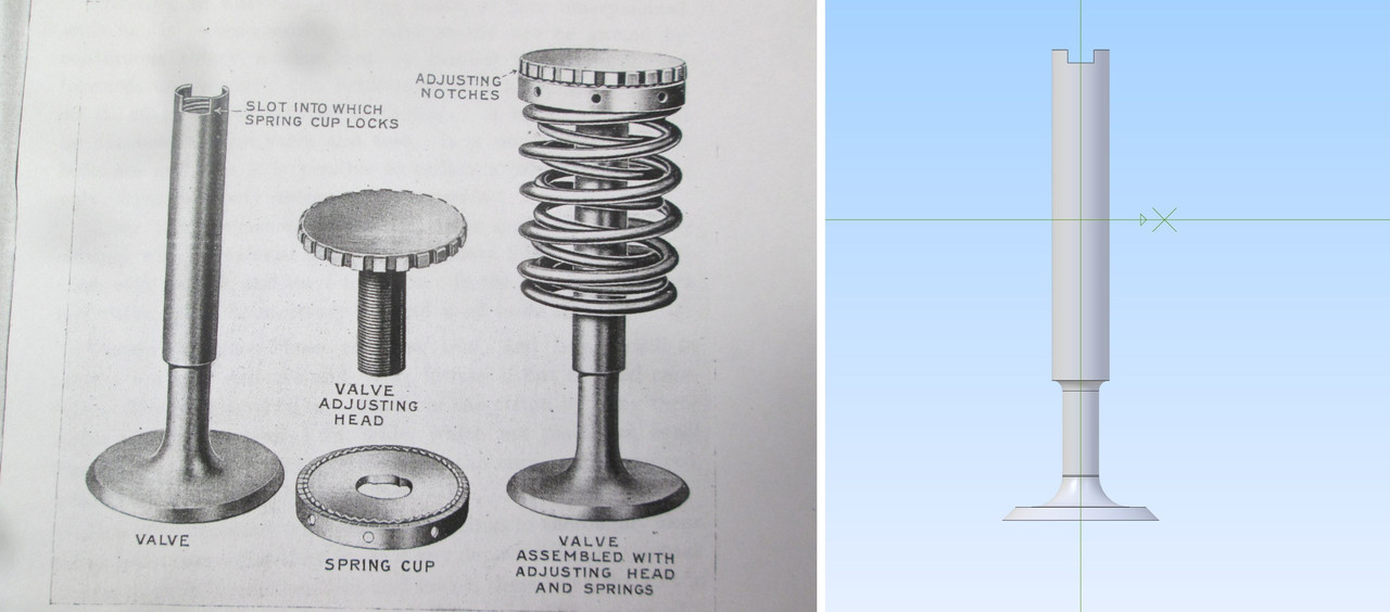
Not everything will be done the way H-S did it; there is a tension between fidelity and my own KISS philosophy, but this detail drawing of the valve and adjusting mechanism is interesting and looks entirely practical to recreate in my shop.
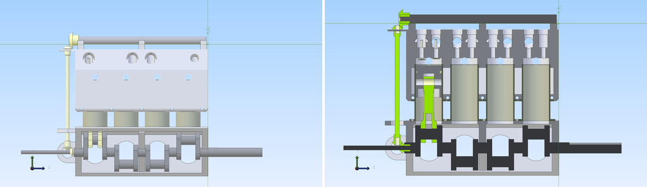
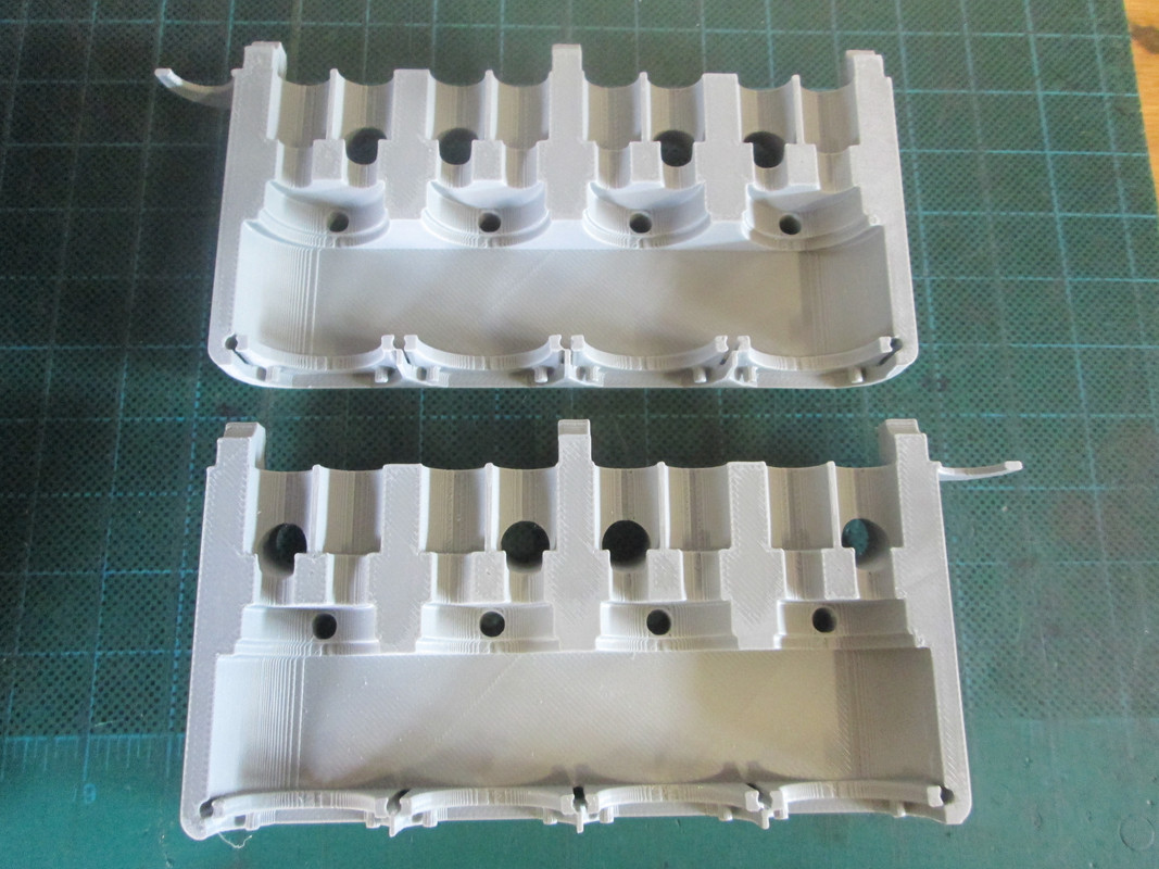
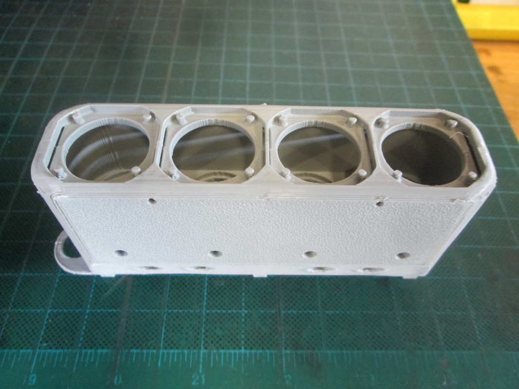
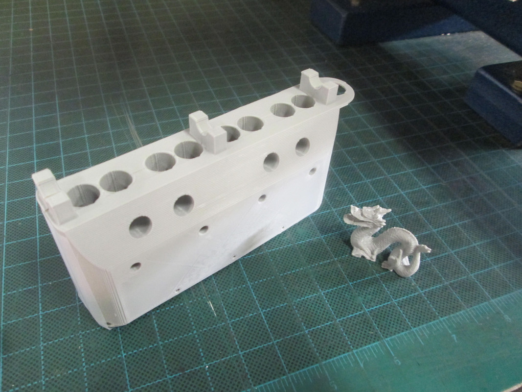
Yes, the basic block, minus the flange sticking out that supports the upper end of the cam drive, is 4.4”. Scaling the drawings used for tracing based on a cylinder bore of 0.75” leads directly to that dimension, as well as a crankcase length that allows the option of line boring on the Taig lathe. A 1” bore diameter doesn't work out as well.
Extending the cylinders to the base of the very top of the combustion chamber as you suggest is an option I've considered, though the drawing shows the other option. I don't yet have a strong preference. Just one of many details to work out and decide on before cutting metal.
Nope, no extra $trillions to found laying around here.