Big stroke 55 cc one cylinder ICE

Started by AlexS · 202 replies · 84,757 views

crueby
Reply #195 · 29 Sept 2026, 13:47
Quote from: Admiral_dkSorry for being a nuisance - but I believe that some of your 3D printed Parts will give you grieves ....

I know for a Fact that PLA and PTEG can't be used with Oil, Gasoline etc.  :ShakeHead:
I made an automatic Chain-Oiler system for my motorcycles and the PLA started to leak almost imidiately - PTEG last for some hours before the Oil starts to seep out through the 'Walls'  :-X

I have no experience with PAHT-CF - but I'm curious about both Oil, Gasoline and Heat Resistance and what your experience will be, when you start to run the Engine ....

Per        :cheers:
Part of the issue with the leaks may not have been compatibility issues with the pla or petg - 3d printed parts, especially ones without 100% infill but even with them, often have tiny spaces where the print head changes direction when laying down the material. Unless it is sealed with something, the surfaces will leak. Thin varnish, epoxy, paint, anything like that will seal the pores and prevent leaks. I learned that with parts made for my RC boats.
Admiral_dk
Reply #196 · 29 Sept 2026, 16:14
I kind of agree Chris - but the same vessels held water for more than a week - before they were tested with Oil  :'(  :hammerbash:    :Director:    :-X

Per            :cheers:
crueby
Reply #197 · 29 Sept 2026, 17:10
Quote from: Admiral_dkI kind of agree Chris - but the same vessels held water for more than a week - before they were tested with Oil  :'(  :hammerbash:    :Director:    :-X

Per            :cheers:

You are right! I - did some searching on oil resistance of the two filaments, and they can handle some oils for short term, over long term they will absorb oil and break down. A lot depends on the kind of oil used!  So, if you need to use a printed part with oils, better seal it very well, or use a different filament material that can handle oils better (I don't know which can).
:cheers:
AlexS
Reply #198 · 29 Sept 2026, 17:50
I agree that how good the printer places layers material is also important to make it leak free.

PAHT-cf would resist hot oil (to 150 deg C) as material only because of PA12 and carbon fiber added (for strength under high temperature).

Printed at high temperature 300 deg C. With 5 wall layers, basically the whole part is build up with only wall layers. The extrusion multiplier is a bit higher. But there could still be microscopic leak paths, before I searched for an epoxy coating but not for now. There are epoxy seals for fuel tanks of motorcycles.

My idea was to give it a try :). It is not for a road vehicle engine, there I should go for metal solution.
Last edit: 29 Sept 2026, 18:18 by AlexS
AlexS
Reply #199 · 1 Oct 2026, 20:20
Oil Sump

The comments give me idea to make a testing oil can. Same settings and material for printing. Put synthetic oil in. Anyway the engine should run with mineral oil for running in. But I understand if right fully synthetic oil with esters and additives would be better to test.

Disassebly bottom engine

I definitely for next engine would made a crankcase of two parts. It is quit messy to remove all rtv gasket from existing aluminum crankcase parts.

The front mainshaft showed eccentric wear where the support bearing is located between distribution belt and fly wheel.
Had to use a pully remover to remove the small bearing with plate.

I might think misalignment of crankshaft/bearinghouse with this small bearing. Or the bearing could slip om internal shaft surface.

Would drill the holes of the aluminum plate of small bearing a bit larger, but would see if I can machine small dowel pins from main bearing houses to side plates. Or make a modification to housing and plate.

Crankcase plates are now ready to mill additional holes and cut outs.

Double Helical Gears

Test milling of final set of gears for balance shafts. Need to adjust roughing not rotational A axis, but horizontal X axis movement. Now the roughing takes to much material and leave no material for engraving bit for finishing job.
Log in to see this image
AlexS
Reply #200 · 10 Oct 2026, 12:19
Double Helical Gears

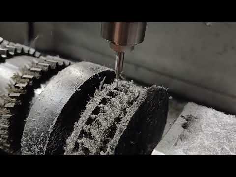
Machined the rest of gears out of POM. Using 0.3 30 deg engraving bit is not the best way to machine POM. Small, fine chips remain stuck to the material. It is possible to remove them with a small plastic brush for the Dremel.

Final machined gear and video showed maching with 1mm 2-flute end mill. Which give much better surface finish. Only downside is that it remove a little bit more material than theoretical model showed. teeth end is theoretical 1 mm thick, with engraving it machined to 1.2 and with 2-flute end mill to 0.8 mm.

It result in a bit more gear backlash. Which for these balance shafts is what I think not a big thing.

Oil Sump

I had still 40 gram PAHT-CF left. I print a small oil test bucket of 10cc. Same parameters as printed sump (5mm thick). I let it stayed with synthetic oil for couple months. Only I can not test it on hot temperature for thinner oil (using now 10W40).

https://youtu.be/l3FS8u2PFWUYouTube video
Log in to see this image
AlexS
Reply #201 · 10 Oct 2026, 12:51
Oil Control Sandwich Plate

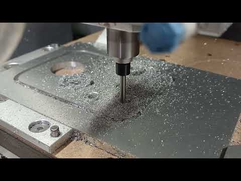
Trying to use the cnc for machining aluminium. The oil control sandwich plate , between oil sump and PRV/filter body, need to machine couple O-ring grooves.

Using here European 1, 2 and 3 mm 2-flute end mills. Sprayed a bit of WD40. If I want to continue machining aluminium on this machine, I need to find a proper mist lubricator. The plate for this sandwich plate was delivered as test example with the machine. Which machined much smoother than the 2nd part, the crankcase back plate.

I broke a couple of 1 and 2 end mills. Not only lubrication but also settings of machining need to be take in account. It is needed to use a certain ramping. Distance of 10 to 20 mm and angle of 3 to 5 degree for larger end mills. I already lowered ramping speed to 50 mm/min. And 150 mm/min feed for  1 and 2 mm end mills and 400 for larger 3 mm.

3 mm can do the job without issues, you can easy hear that in sound.

Other settings I changed is step over of 20 to 30 % of diameter of mills. For cutting direction climb milling.

But for pocked milling. Or Contour milling. It still need to start with full 100% diameter.

I am not sure if 1 or 2 flute would perform better on these hard aluminium.


Crankcase Back Plate

I want to re use and modify the front and back crankcase plates.

The plate need to fit two balance shaft support blocks. And so these need to be correct positioned according to main shaft bearing and shaft seal.

The current hole of main shaft was already in the correct position +-0.5mm.


As suggested in previous post, the alignement of crankshaft bearing blocks to crankcase plates need to be improved. Well, it would be nice if I modify the bearing blocks with a lid to fit in the crankcase plates.

The bearings would be placed 2x2mm to the wider. Which only need thicker POM axial spacers between bearings and crankshaft.

The crankshaft need to be disassembled anyway. To fit new connecting rod, big end. And would see if I can machine a new front main shaft of C45 (because it has significant wear mark of flywheel support bearing).

https://youtu.be/7Y2mGLSCWxQYouTube video
Fuel Tank Air Logic ©

Well.. It all started with a printed piston. To use the engine as standalone and with sump it would be much higher to fit old fuel tank. Why to fixate it to the engine. The engine should not vibrate to much to current state.

POM 10mm thick isolation blocks between intake manifold (still need to have some reinforcement). 550 cc would be enough to run this engine couple of hours.

Have still some epoxy tank cure coating here laying around to seal it.

Log in to see this image
Last edit: 10 Oct 2026, 12:56 by AlexS

Quick reply

Log in to reply.