Interesting project!
Offtopic, last week visit National Military Museum in Soesterberg NL. First time saw the a huge Hispano engine not the V8 but a V12, and a Merlin and rotary and radial engines.
AlexS
Full Member · NL · Joined Jan 2018 · Last active 2d ago
Full MemberMember
About
- This member hasn't added anything here yet.
Recent posts
All posts- In topic · 3d ago
- In topic · 12d agoThanks Jason!
- In topic · 13d agoHi!
How was last Midlands Model Engineering Exhibition going on? - In topic · 25d agoOil Control Sandwich Plate
Trying to use the cnc for machining aluminium. The oil control sandwich plate , between oil sump and PRV/filter body, need to machine couple O-ring grooves.
Using here European 1, 2 and 3 mm 2-flute end mills. Sprayed a bit of WD40. If I want to continue machining aluminium on this machine, I need to find a proper mist lubricator. The plate for this sandwich plate was delivered as test example with the machine. Which machined much smoother than the 2nd part, the crankcase back plate.
I broke a couple of 1 and 2 end mills. Not only lubrication but also settings of machining need to be take in account. It is needed to use a certain ramping. Distance of 10 to 20 mm and angle of 3 to 5 degree for larger end mills. I already lowered ramping speed to 50 mm/min. And 150 mm/min feed for 1 and 2 mm end mills and 400 for larger 3 mm.
3 mm can do the job without issues, you can easy hear that in sound.
Other settings I changed is step over of 20 to 30 % of diameter of mills. For cutting direction climb milling.
But for pocked milling. Or Contour milling. It still need to start with full 100% diameter.
I am not sure if 1 or 2 flute would perform better on these hard aluminium.
Crankcase Back Plate
I want to re use and modify the front and back crankcase plates.
The plate need to fit two balance shaft support blocks. And so these need to be correct positioned according to main shaft bearing and shaft seal.
The current hole of main shaft was already in the correct position +-0.5mm.
As suggested in previous post, the alignement of crankshaft bearing blocks to crankcase plates need to be improved. Well, it would be nice if I modify the bearing blocks with a lid to fit in the crankcase plates.
The bearings would be placed 2x2mm to the wider. Which only need thicker POM axial spacers between bearings and crankshaft.
The crankshaft need to be disassembled anyway. To fit new connecting rod, big end. And would see if I can machine a new front main shaft of C45 (because it has significant wear mark of flywheel support bearing).
https://youtu.be/7Y2mGLSCWxQ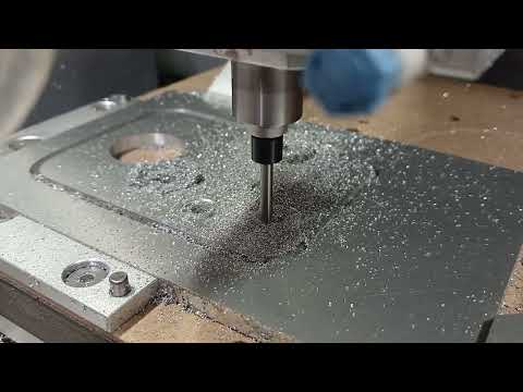
Fuel Tank Air Logic ©
Well.. It all started with a printed piston. To use the engine as standalone and with sump it would be much higher to fit old fuel tank. Why to fixate it to the engine. The engine should not vibrate to much to current state.
POM 10mm thick isolation blocks between intake manifold (still need to have some reinforcement). 550 cc would be enough to run this engine couple of hours.
Have still some epoxy tank cure coating here laying around to seal it. - In topic · 26d agoDouble Helical Gears
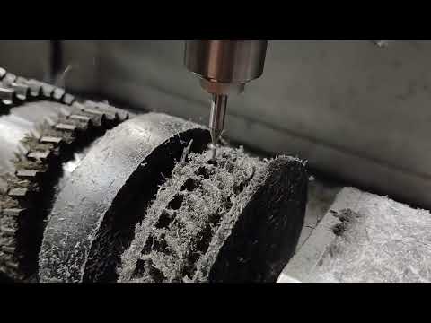
Machined the rest of gears out of POM. Using 0.3 30 deg engraving bit is not the best way to machine POM. Small, fine chips remain stuck to the material. It is possible to remove them with a small plastic brush for the Dremel.
Final machined gear and video showed maching with 1mm 2-flute end mill. Which give much better surface finish. Only downside is that it remove a little bit more material than theoretical model showed. teeth end is theoretical 1 mm thick, with engraving it machined to 1.2 and with 2-flute end mill to 0.8 mm.
It result in a bit more gear backlash. Which for these balance shafts is what I think not a big thing.
Oil Sump
I had still 40 gram PAHT-CF left. I print a small oil test bucket of 10cc. Same parameters as printed sump (5mm thick). I let it stayed with synthetic oil for couple months. Only I can not test it on hot temperature for thinner oil (using now 10W40).
https://youtu.be/l3FS8u2PFWU