Emergency Engine - Radial Wobbler Engine

Started by propforward · 27 replies · 2,079 views

propforward
18 Sept 2026, 00:49
Right so,

I'm signed up to display my THREE engines that I have on hand at the Indiana Engine Show in October. My friend there who is part of the organizing squad asked "how many tables do you need?"

Er. How about 1/8? That should be more than enough.

So in an attempt to fill up the table a bit I am trying to make SOMETHING. What I settled on was a multi cylinder wobbler - one of Elmers designs - which I have scaled up so that it fills up more of the table. It's simple enough, interesting enough and there's a slim but real chance that I can get it done in time. Once finished, I will publish the plans, but I'm fixing them up as I go.

I won't tell you which Elmer it is yet, but it will be pretty obvious soon enough to anyone familiar.

The start. Sawing stuff. Making use of my own design, quick release jacking screw on the 4X6 saw, which works really well. This is really the only reason for showing this pic.
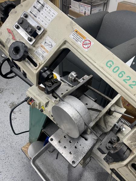


This big chunk of aluminium was given to me along with a lot of other very nice material drops by Topper Machine, a machining channel you may - or may not - have happened upon on the You Tube. In fact, the majority of material for this is drops he supplied - I don't want to spend money on this engine, it's all from what's laying around.

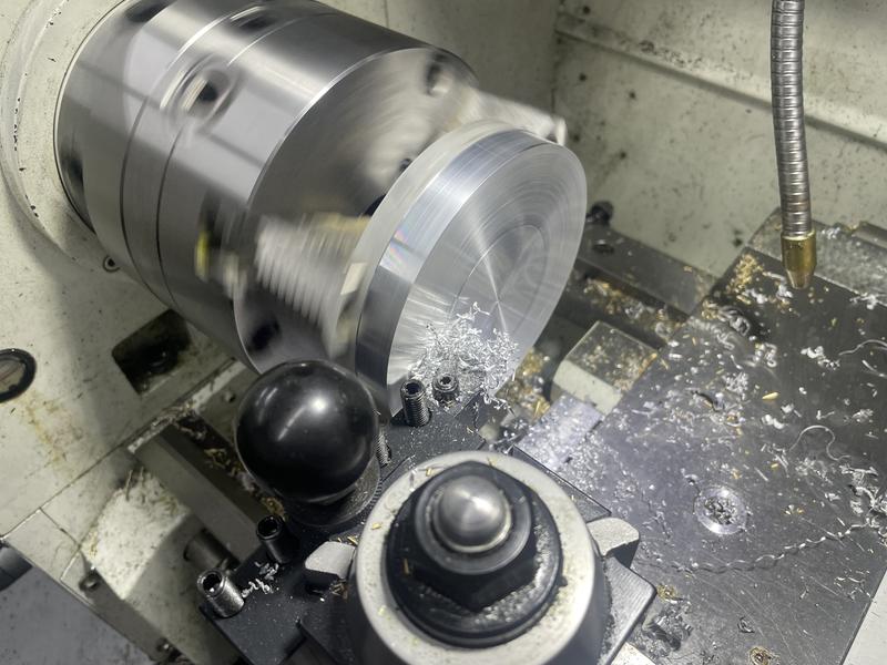
This is going to be the base - not much to it.


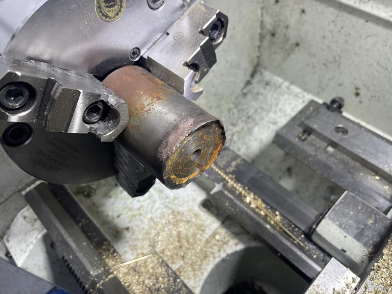
Anyway, I have this nice piece of brass rod, from which the cylinders shall hopefully emerge. The idea here is to turn the OD so that the 4 reuired cylinders are very close in size, so that I can gang them up and machine them in single set ups. I will tell you now that this mostly worked.

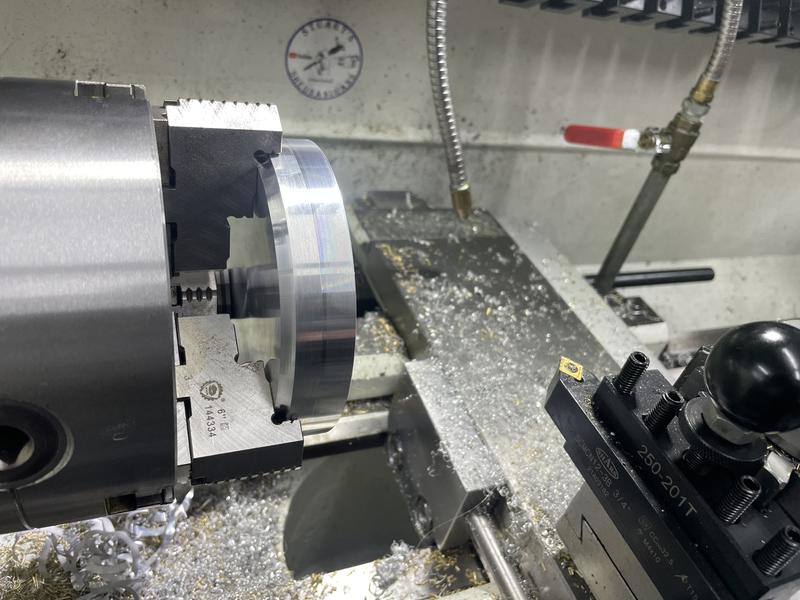
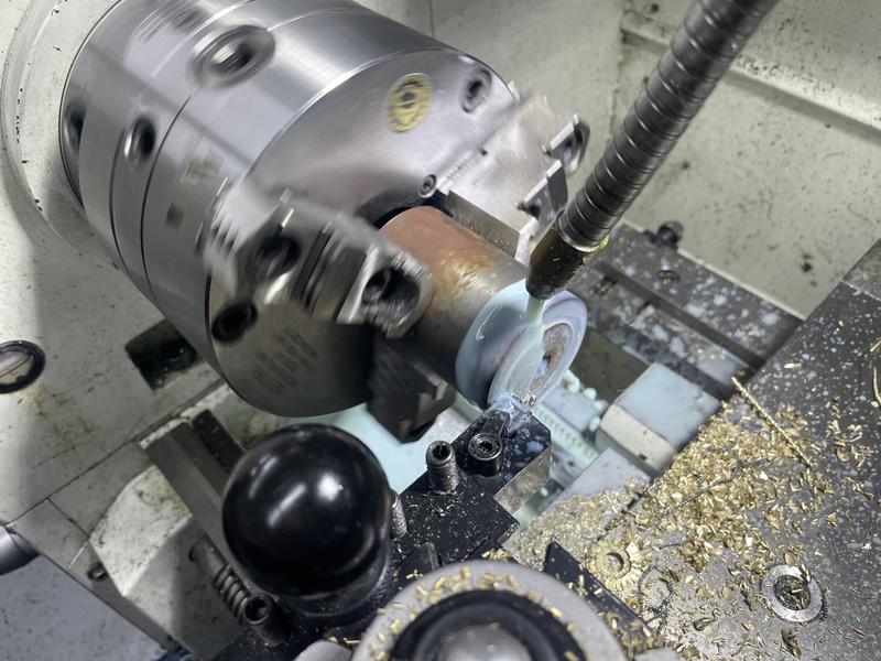
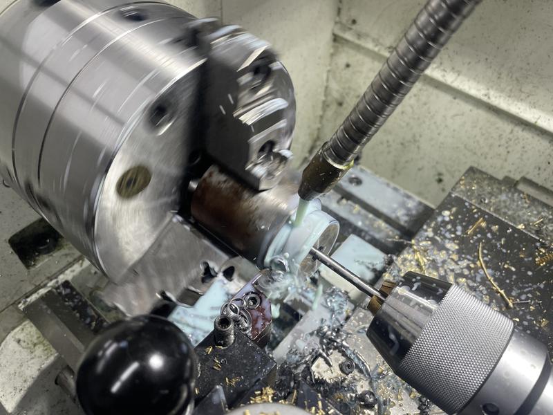
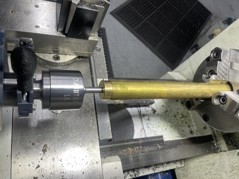
Supporting on a revolving center, and turned to 1.0"


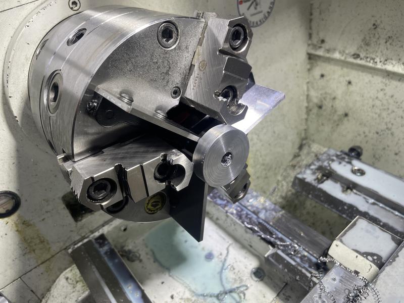
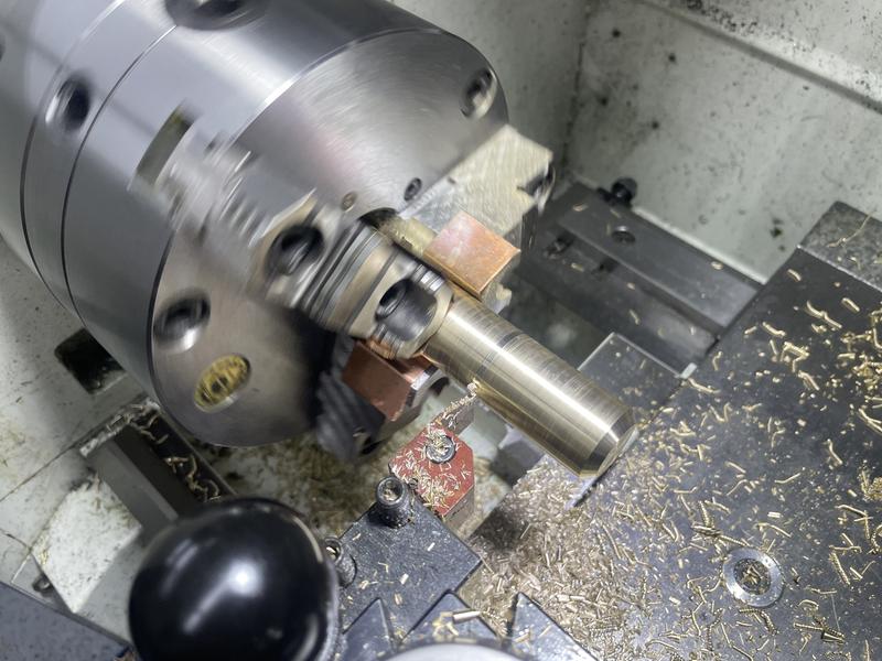
Then chamfer one end, and part off with about .020" of stock on the parted end. The chamfer isn't needed. Just for some kind of visual appeal.


Then measured all 4, and noted on each piece how much to take off.
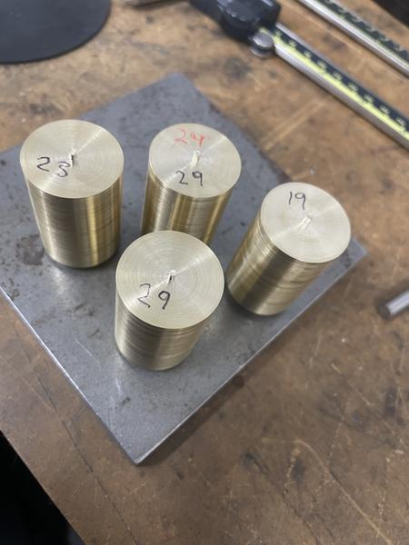


Just skimmed them to length after that.

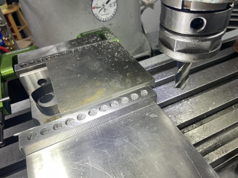
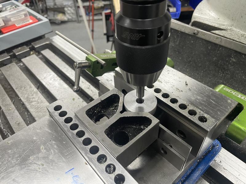
Then to the mill, all ganged up together. The idea was to find center of the block of 4 pieces, then move out to the center of each piece. Because the variation of diameter on all 4 cylinders was under .001", this worked like a charm without serious tolerance stack up. Talk about quick and dirty but it worked out.
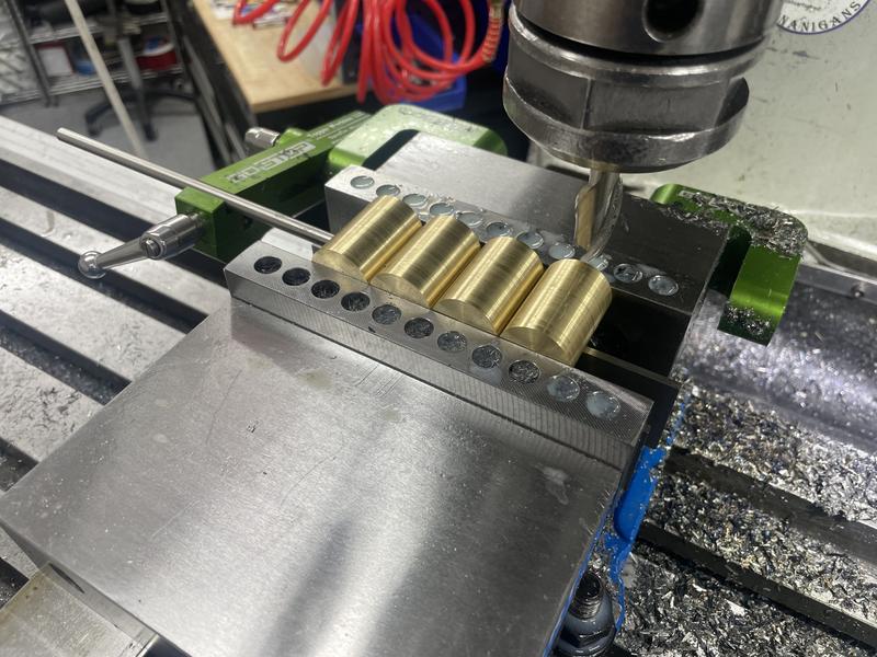


I did end up using a piece of soft aluminium wire on the moving jaw to take up minor amounts of variance in the parts, and they stayed solid.

Flats, spotface, locating hole for the pivot shaft and port all in place:
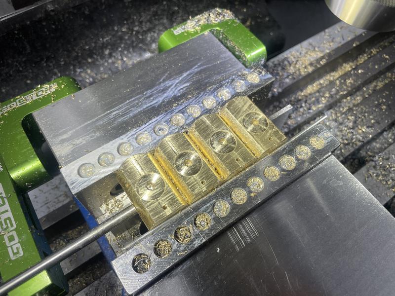


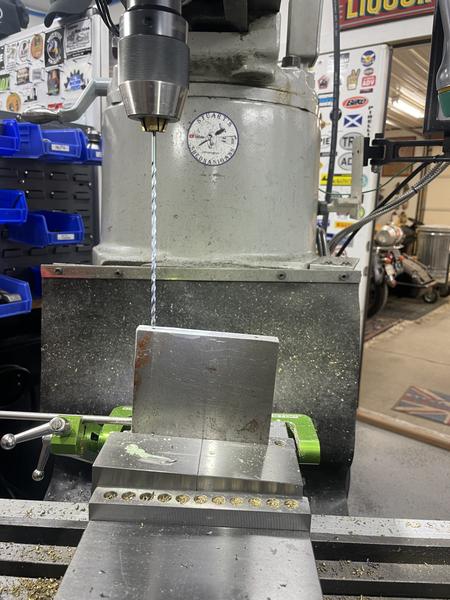
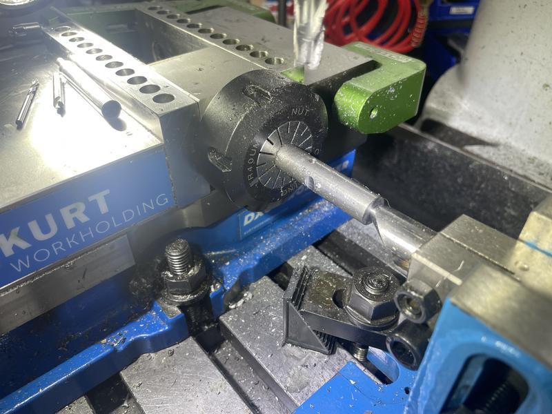
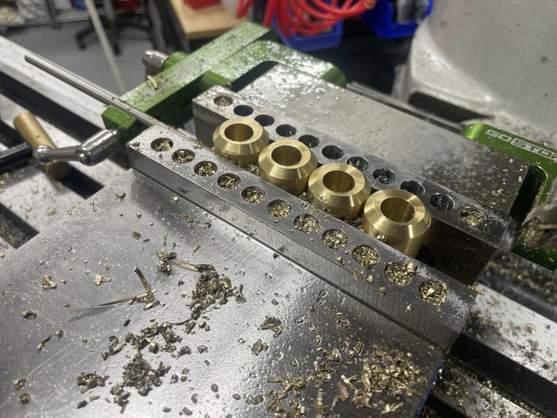
Then upended them - flat surface registered against the fixed jaw, center of the group found again, and the bore was drilled to depth, then cleaned out to size with a 1/2" end mill. The bore is off center from the turned diameter, or I'd have done the bore in the lathe.
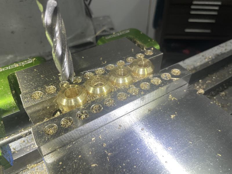


This may seem a rather half arsed approach, but a 1/2" gauge pin fits the bores perfectly. I didn't have an end mill suitably under size to allow use of a reamer, and decided if the bores were over I would just make the pistons to suit. Not my normal approach, just having fun with it.
propforward
Reply #1 · 18 Sept 2026, 01:00


Moving on, I need a plate to mount everything on, so rough sawed a piece of 1/2" thick cold rolled that was laying about, thrown out from a prior company I worked at, and set about it with reckless abandon.


Basically milling it square there.

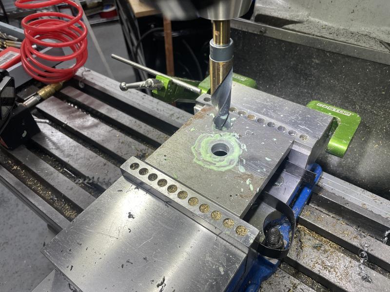
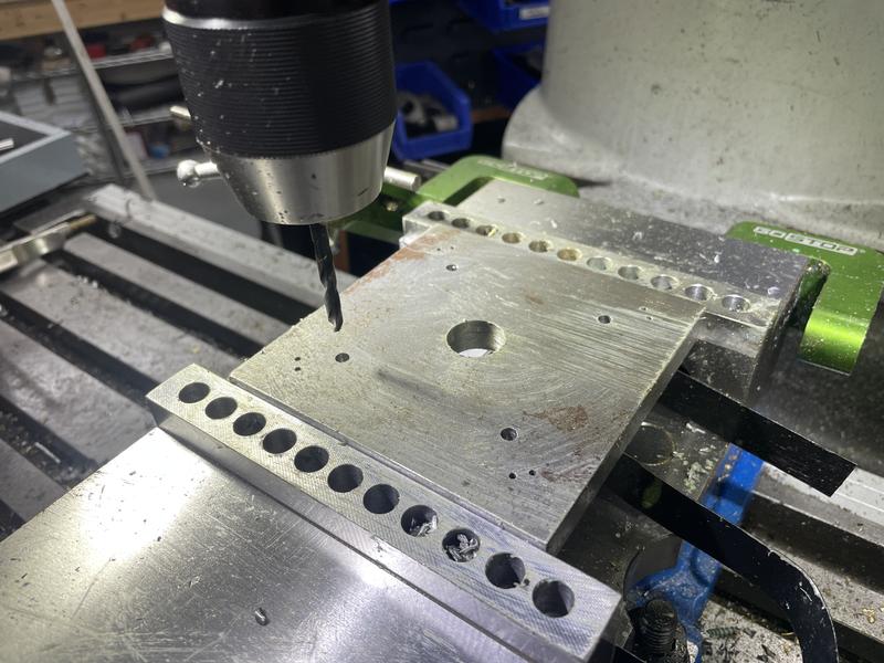
The really fun bit, which turned into a minor issue, was drilling long ports through the plate. Regular jobber bits are not long enough, so I procured a long tool to proudly display.


These long ports have to be drilled at a slight angle so as to clear the through holes for the exhaust, but intersect with the inlet holes that only go half way through the plate.

In the end, I did indeed break the drill in one of the long holes, and had to drill from the opposite end in order to knock the broken off drill bit out. If you want to see the sheDnanigans involved with that, it's in this vaguely amusing video. I didn't take any pics of the recovery, unfortunately.

https://www.youtube.com/watch?v=g59fjNFB_n8&t=202sYouTube video
55fairlane
Reply #3 · 18 Sept 2026, 01:06
A quick and minor tip if I may....do not break the drill off in the work.....its a pain yo remove.......
propforward
Reply #4 · 18 Sept 2026, 01:07
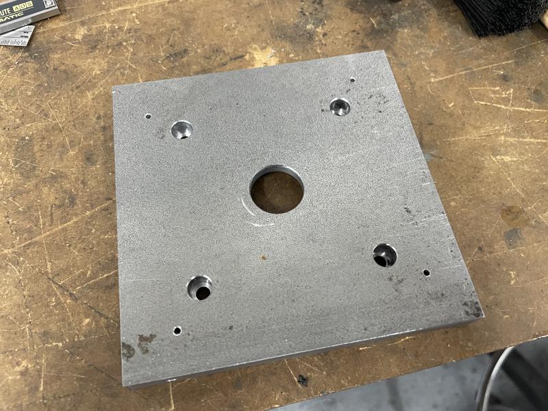
The rest of the features on the plate went easily enough. I have to plug the ends of a couple of passages, and clean up the front and back so they are smooth. I might fly cut them, but will likely just DA them with an orbital sander.

Drill through hole to mount a plain bearing:


Drilled the port holes - locating these is easy with a DRO, but Elmers original design suggests making a drilling jig. I used that approach on my first wobbler and it worked great. Also drilled the through holes for the cylinder pivots.


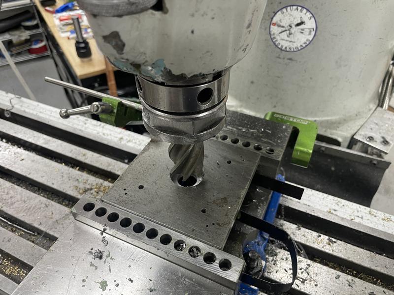
I took the quick and dirty way again, cleaned out a fair bit of material for the crank disc counterbore with a 1-1/4" end mill:


Backside got counterbores to secure springs on the pivots:


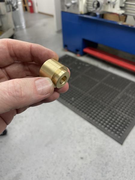
I also quickly turned up a brass plain bearing for the crankshaft:


propforward
Reply #5 · 18 Sept 2026, 01:07
Quote from: 55fairlaneStuart,  so far so good.....looking forward to seeing it runs in person


Thank you. Me too!
propforward
Reply #6 · 18 Sept 2026, 01:08
Quote from: 55fairlaneA quick and minor tip if I may....do not break the drill off in the work.....its a pain yo remove.......


Next time tell me BEFORE I screw up!  :ROFL:
propforward
Reply #7 · 18 Sept 2026, 01:12
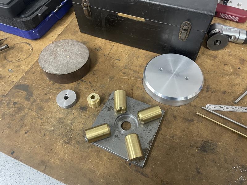
I found this lump of gnarly something or another, and decided it would be a crank disc.


Off to the mill with it. Locate the bore with a close fitting gauge pin:


Then offset and drill and ream for a crank pin.

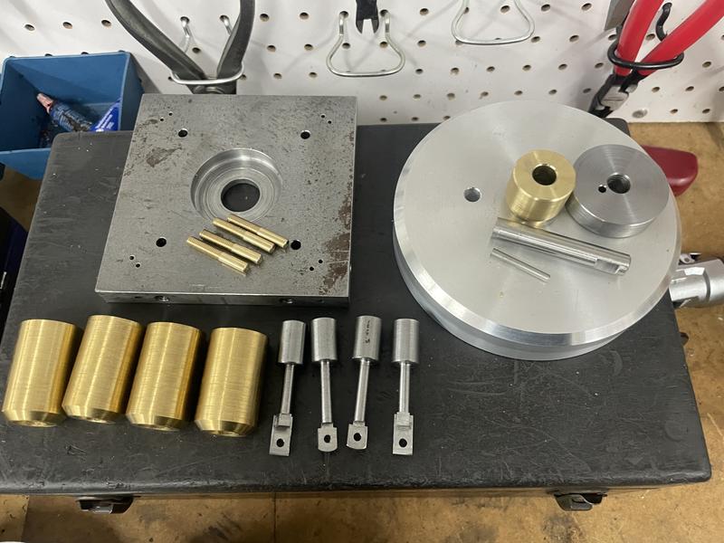
Bringing us to this motley collection of parts, and rough sawn lump of something else, which shall be the flywheel when I get to that.


Next up, pistons, crankshaft and crank pin.

And cylinder pivots. I have the upcoming weekend, and one more to get this done, which should be entirely possible.
propforward
Reply #10 · 20 Sept 2026, 19:02
Thank you Gents,

It's a blocky sort of an engine, not very ornate, but that said I'm having a blast just charging through this.

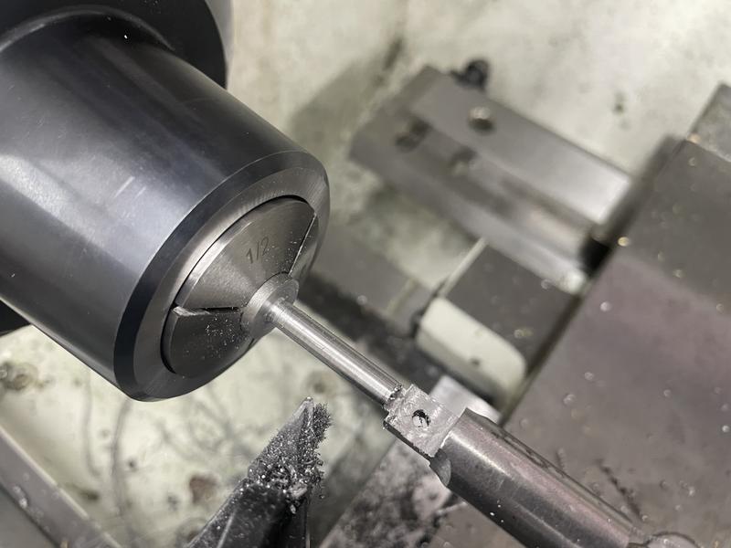
The pistons are a little bit of a challenge, and machining sequence is fairly important to prevent heartache.

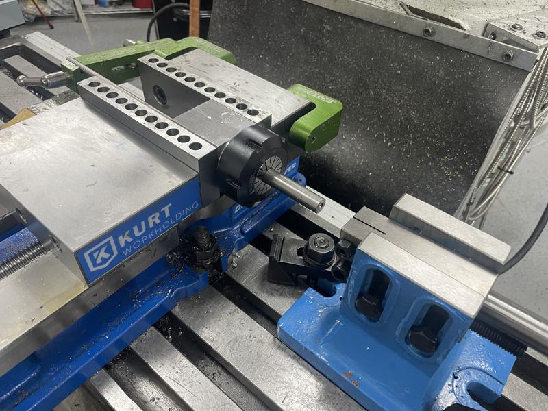
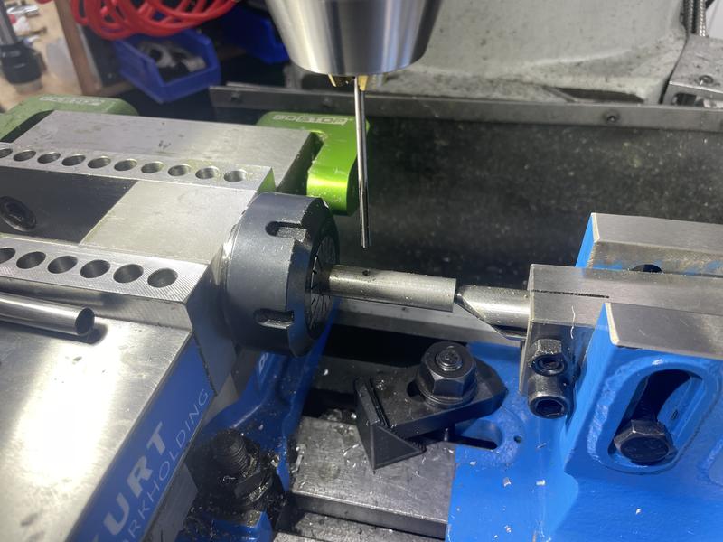
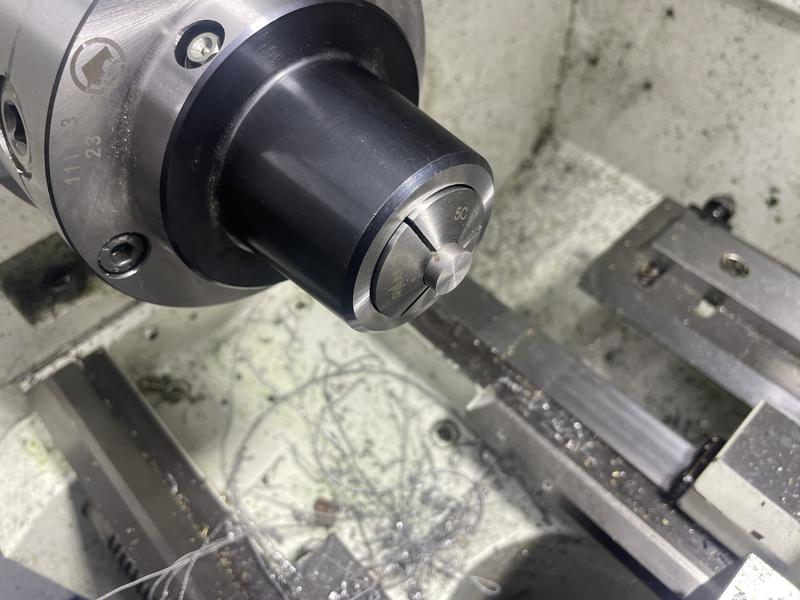
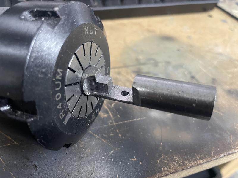
To do it I cut blanks for each piston with extra material each end (for holding onto later). Both ends were faced square and one end got a center in it. This was for support in the mill.


First operation was to drill and ream the hole for the crank pin.


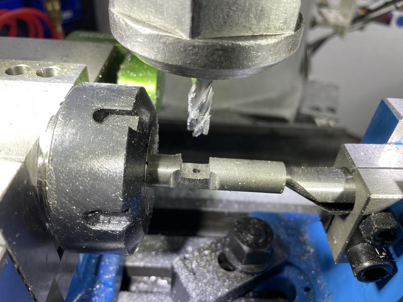
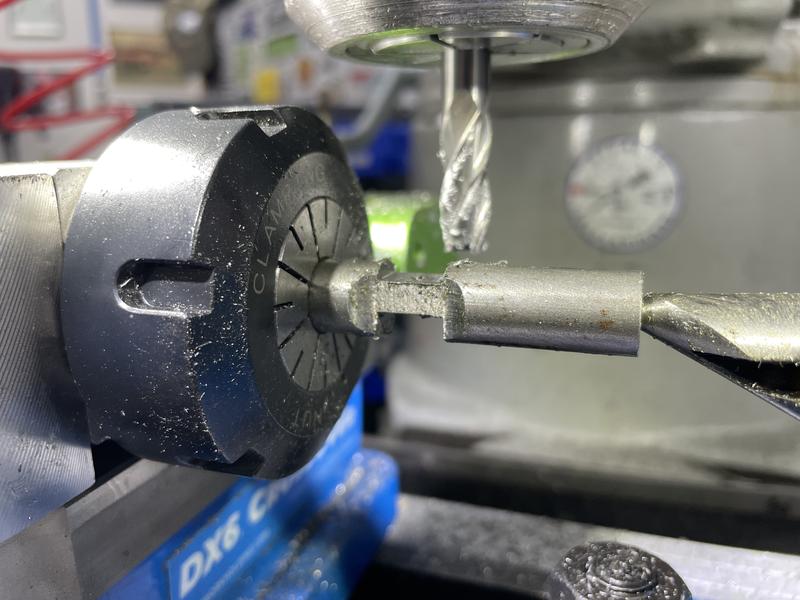
Then, rather than machine the rod to diameter, I machined all the cut outs and flats for the con rod big end first.

Side clearances:


Then machined away material to leave the flat:


Because I'm using a square collet block, it was easy to flip the part 180° and machine away the opposit side as needed.


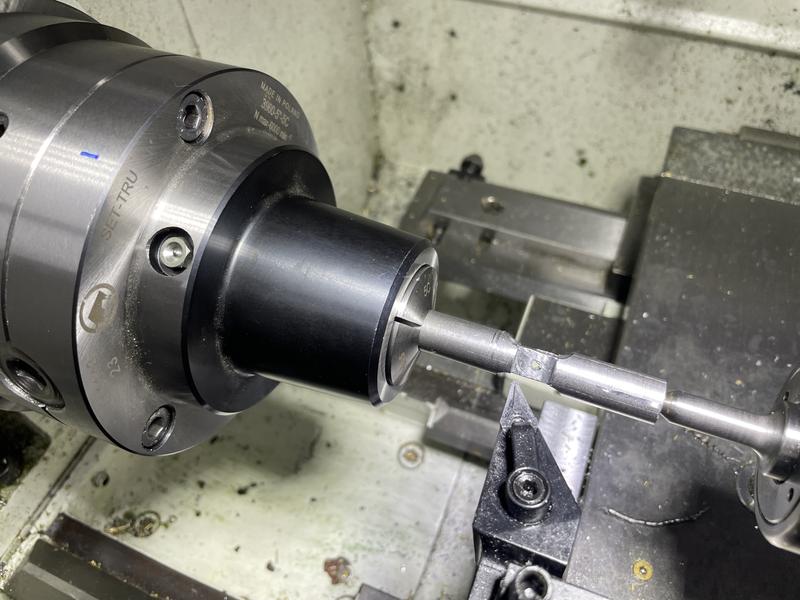
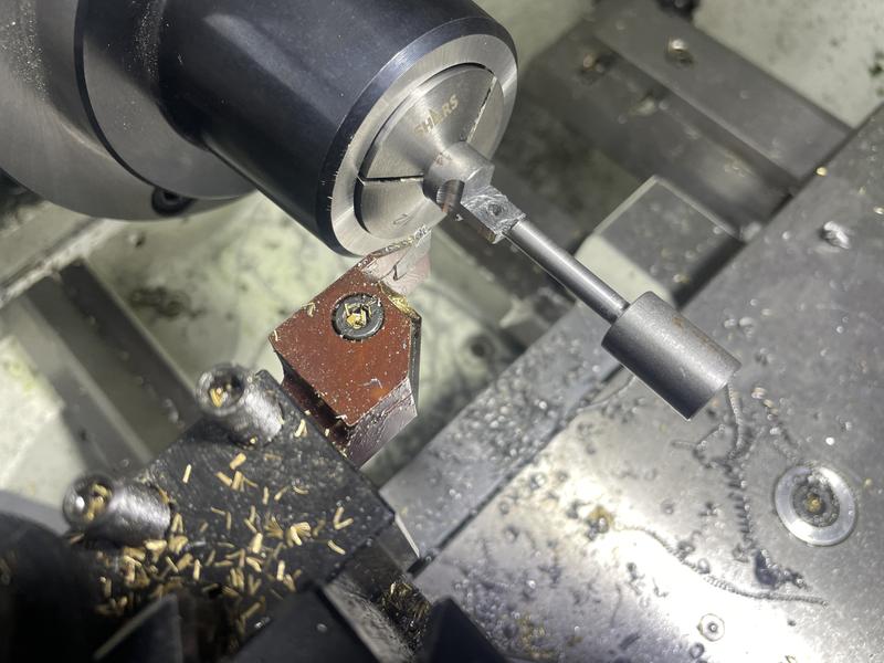
Once all the milling work was complete, it was over to the lathe for the remaining features. Turn the con rod portion first. The end of the part with the center in is used as the zero datum for all machining ops, so it's easy to transfer between mill and lathe.


The part was then turned around, and the piston turned to length


Then pulled out - and you can see now how handy having the extra piece of material on the con rod end is. Now the completed piston is just parted off.


I put a little radius on the end of the con rod by hand on a belt sander.


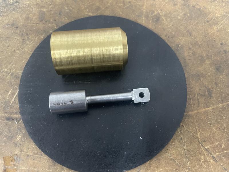
The finish isn't very good on the cylinder. It feels smooth, just doesn't look great. I'll take some scotchbrite to those.

I didn't put oil grooves in the piston because I don't think they'll be needed for how infrequently this engine will run.

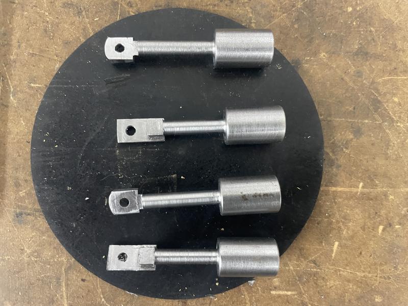
There are two pairs of pistons on this engine. Made in a similar way, but with slightly different con rod ends, as all 4 nest together. Here is the other piston type part way through milling.


All 4 pistons complete (still need some deburring)


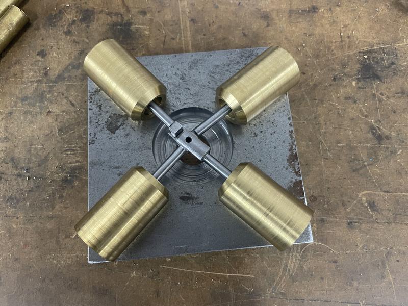
And gathered together in a vague demo of the engine layout.

propforward
Reply #11 · 20 Sept 2026, 19:05
I also made some of the other simpler pieces, like pivot rods, crank pin and crank shaft. Didn't take pics of the process because those are pretty basic.

Here is the collection of parts:


So now I need to do some finishing (DA the engine plate, weld a few of the through passages shut at one end) and make the flywheel. I also need to make a barb fitting for compressed air inlet.

propforward
Reply #13 · 21 Sept 2026, 12:33
I hope it works. Even if it doesn't, it will be an extra thing on the table.

Wobblers are pretty tolerant though. Should be OK.
55fairlane
Reply #14 · 21 Sept 2026, 15:18
You are good machinist,  have faith and you will be blessed with a running engine

Quick reply

Log in to reply.