I'm signed up to display my THREE engines that I have on hand at the Indiana Engine Show in October. My friend there who is part of the organizing squad asked "how many tables do you need?"
Er. How about 1/8? That should be more than enough.
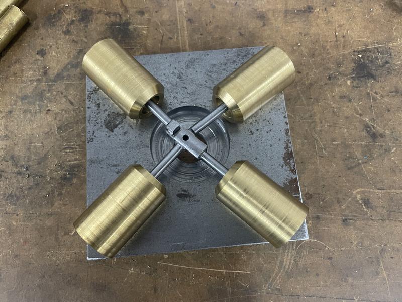
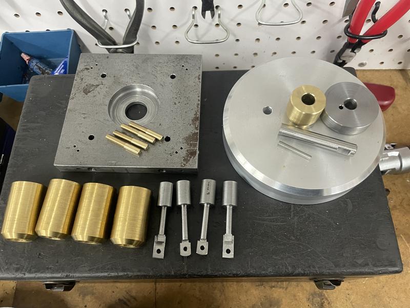
So in an attempt to fill up the table a bit I am trying to make SOMETHING. What I settled on was a multi cylinder wobbler - one of Elmers designs - which I have scaled up so that it fills up more of the table. It's simple enough, interesting enough and there's a slim but real chance that I can get it done in time. Once finished, I will publish the plans, but I'm fixing them up as I go.
I won't tell you which Elmer it is yet, but it will be pretty obvious soon enough to anyone familiar.
The start. Sawing stuff. Making use of my own design, quick release jacking screw on the 4X6 saw, which works really well. This is really the only reason for showing this pic.
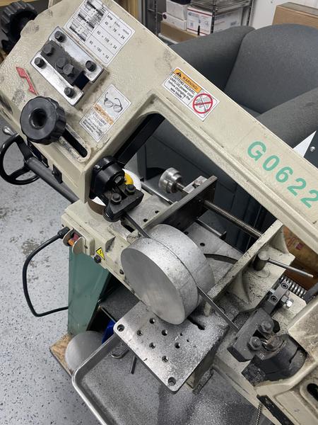
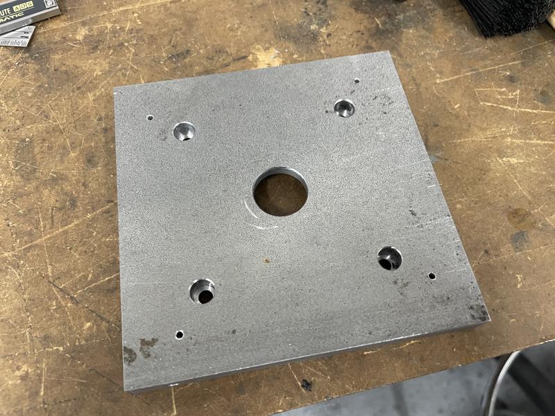
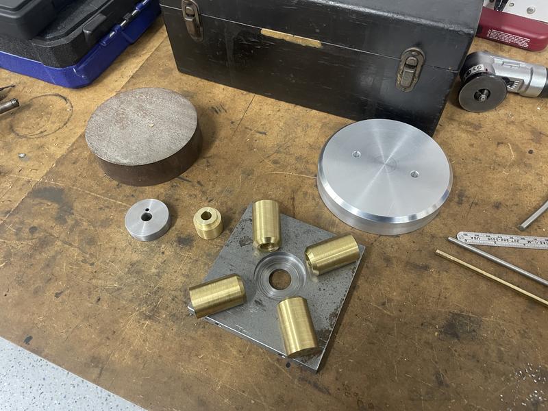
This big chunk of aluminium was given to me along with a lot of other very nice material drops by Topper Machine, a machining channel you may - or may not - have happened upon on the You Tube. In fact, the majority of material for this is drops he supplied - I don't want to spend money on this engine, it's all from what's laying around.
This is going to be the base - not much to it.
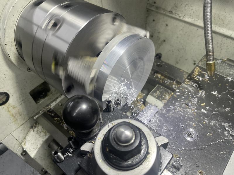
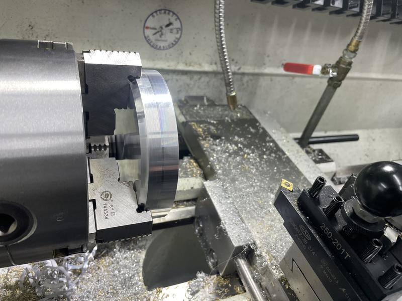
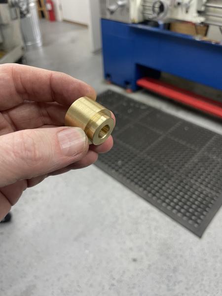
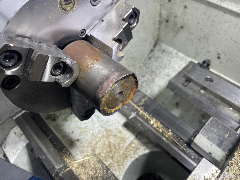
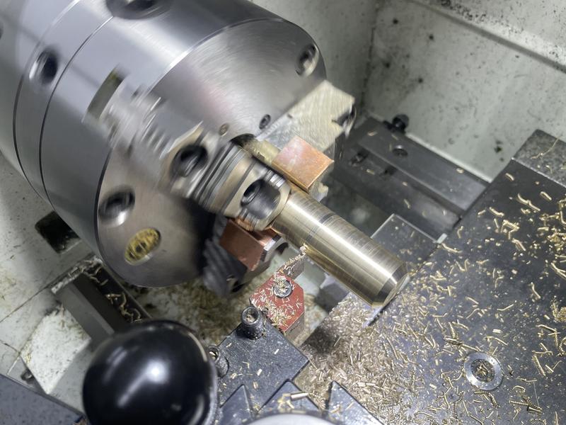
Anyway, I have this nice piece of brass rod, from which the cylinders shall hopefully emerge. The idea here is to turn the OD so that the 4 reuired cylinders are very close in size, so that I can gang them up and machine them in single set ups. I will tell you now that this mostly worked.
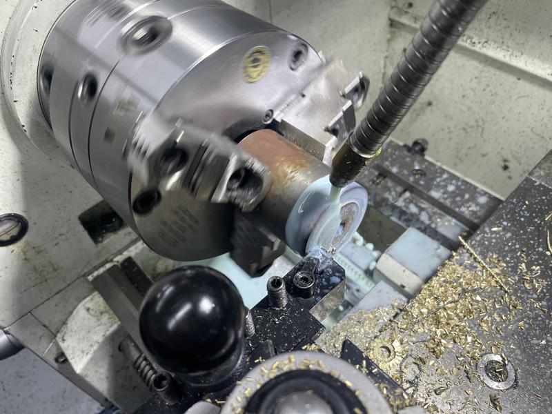
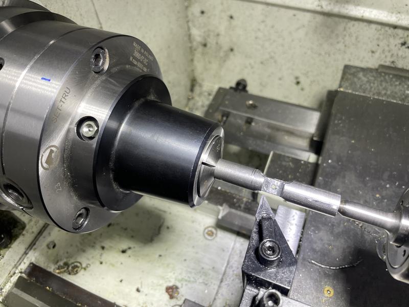
Supporting on a revolving center, and turned to 1.0"
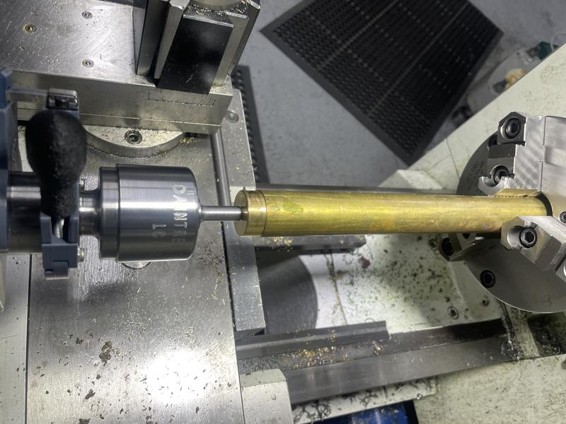
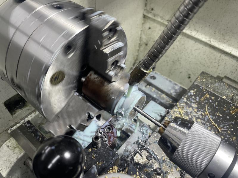
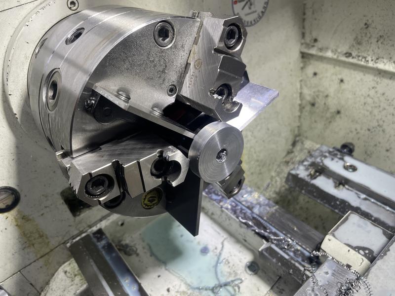
Then chamfer one end, and part off with about .020" of stock on the parted end. The chamfer isn't needed. Just for some kind of visual appeal.
Then measured all 4, and noted on each piece how much to take off.
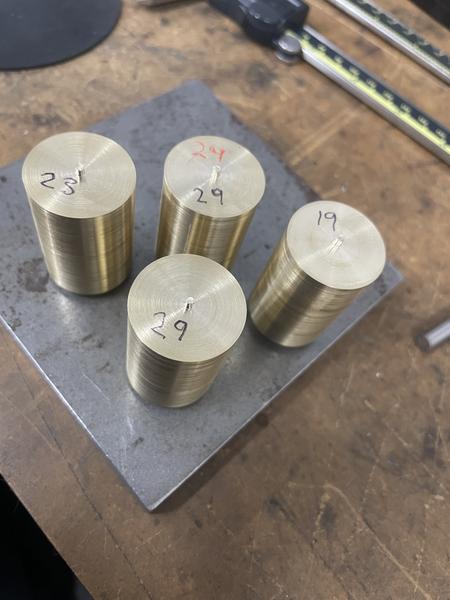
Just skimmed them to length after that.
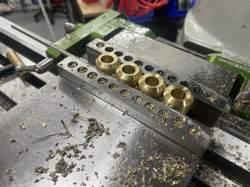
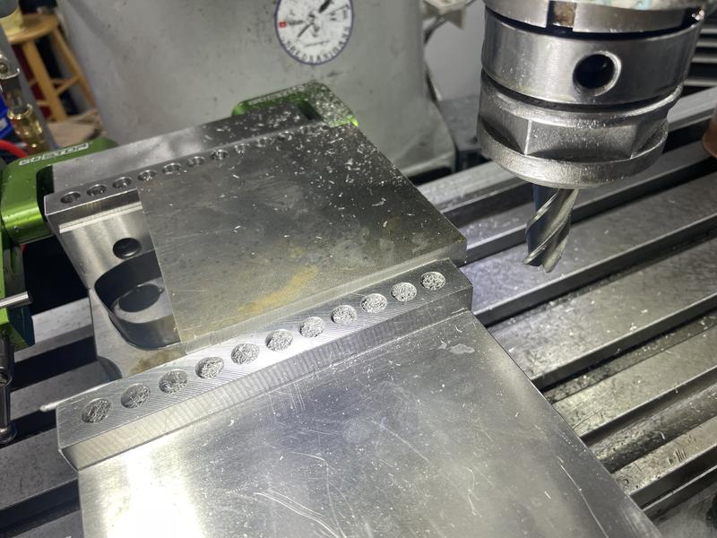
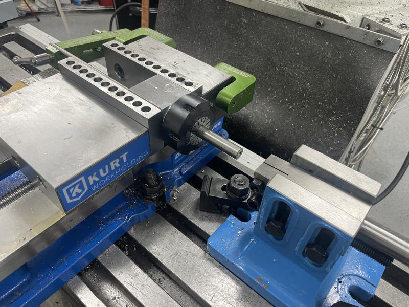
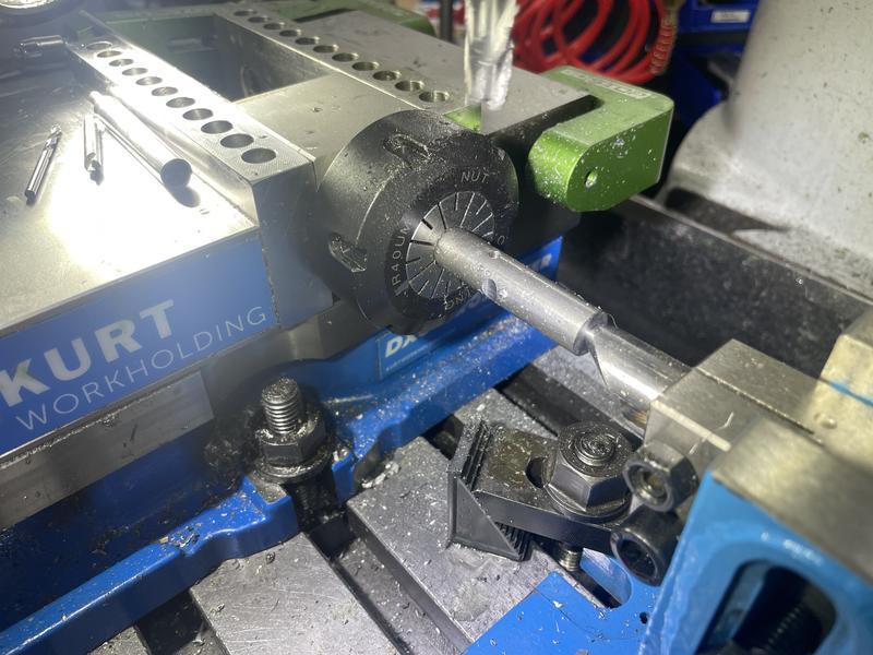
Then to the mill, all ganged up together. The idea was to find center of the block of 4 pieces, then move out to the center of each piece. Because the variation of diameter on all 4 cylinders was under .001", this worked like a charm without serious tolerance stack up. Talk about quick and dirty but it worked out.
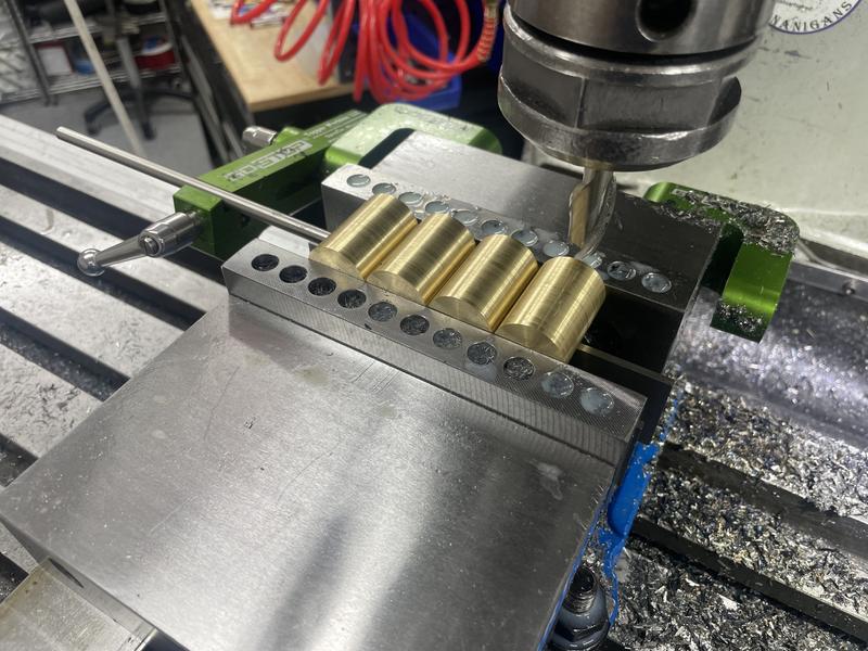
I did end up using a piece of soft aluminium wire on the moving jaw to take up minor amounts of variance in the parts, and they stayed solid.
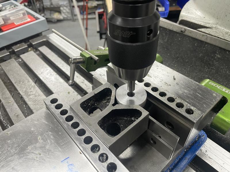
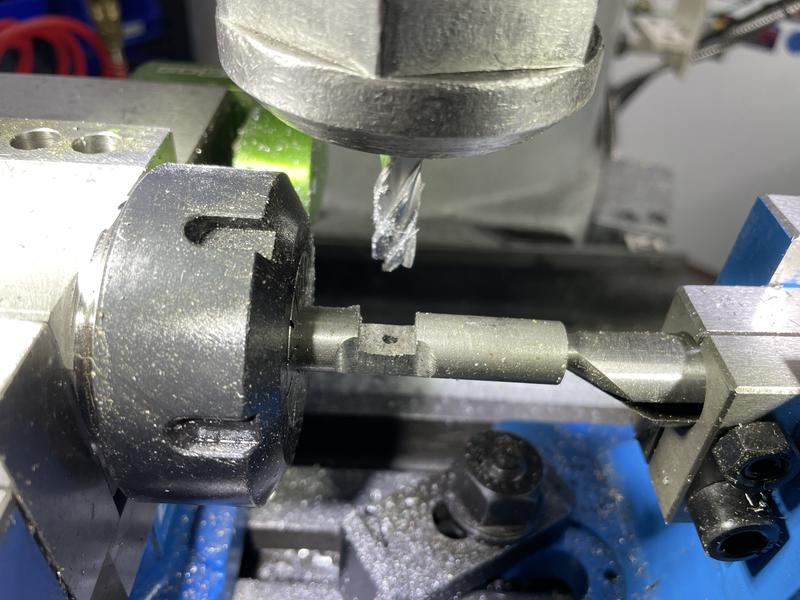
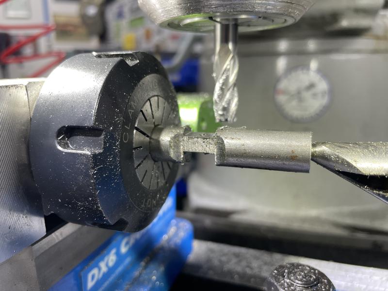
Flats, spotface, locating hole for the pivot shaft and port all in place:
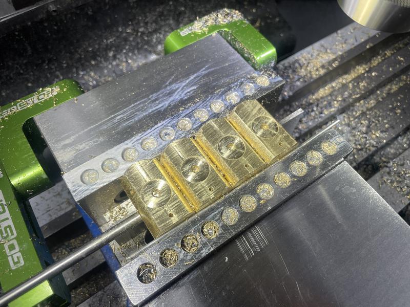
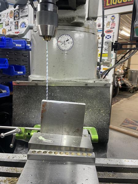
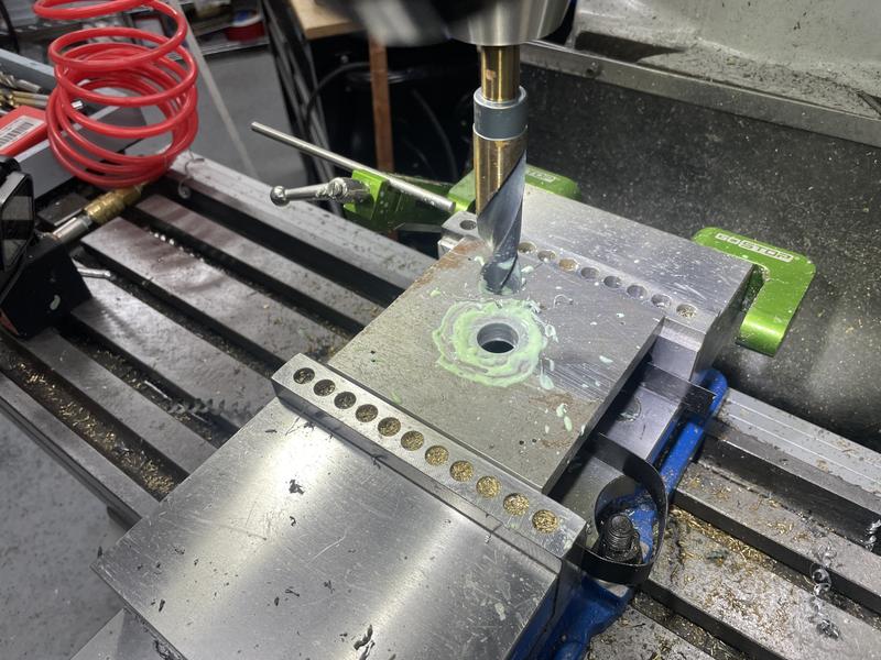
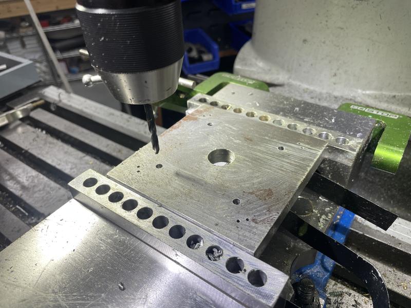
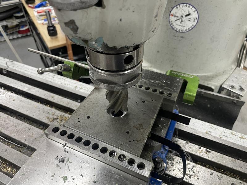
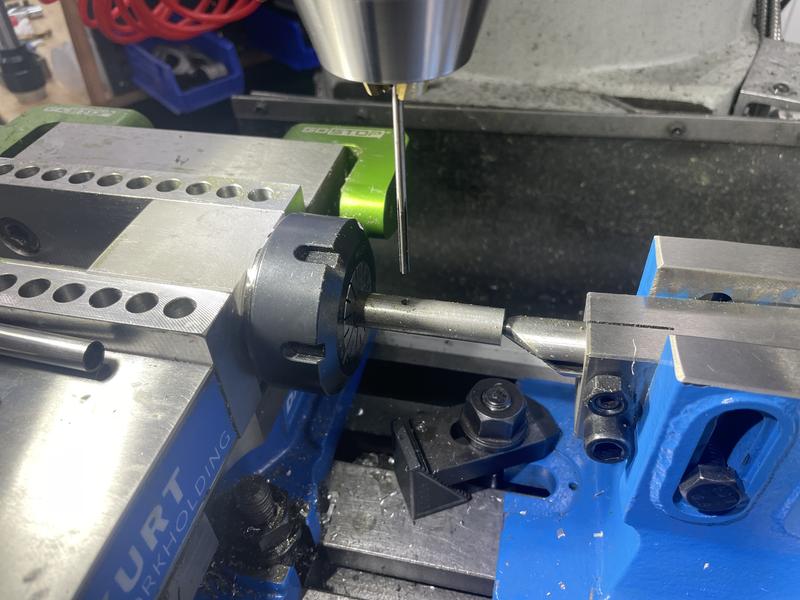
Then upended them - flat surface registered against the fixed jaw, center of the group found again, and the bore was drilled to depth, then cleaned out to size with a 1/2" end mill. The bore is off center from the turned diameter, or I'd have done the bore in the lathe.
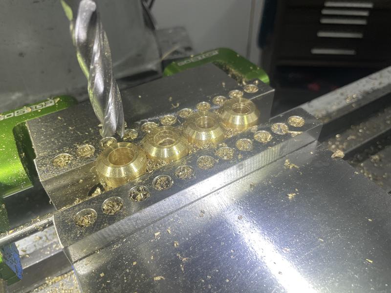
This may seem a rather half arsed approach, but a 1/2" gauge pin fits the bores perfectly. I didn't have an end mill suitably under size to allow use of a reamer, and decided if the bores were over I would just make the pistons to suit. Not my normal approach, just having fun with it.