Ball Bearing Clock

Started by Krypto · 59 replies · 5,012 views

Krypto
13 Jul 2026, 01:31
A few of us have already made some of Steve Peterson's 3D printed clocks.  They work well and are interesting to watch.  Last night he dropped one of his more interesting designs: a clock powered by the weight of ball bearings.  One hundred twenty five 3/4" balls to be specific.

YouTube video

This thing is a monster!  Doubt I would want to tackle this one, but it is interesting design nonetheless.  If you go to his website here:

https://www.stevesclocks.com/sp17

You can download the assembly manual for free.  Towards the back of the manual he goes over his design decisions which I found interesting to read.
krt2
Reply #1 · 13 Jul 2026, 03:32
That's pretty cool!  I may have to make me one of those! :)

Kim
wagnmkr
Reply #2 · 13 Jul 2026, 10:33
Thanks Krypto (I think)

That is a very different looking clock to be sure and would definitely be a conversation starter!

Having made 5 of Steve's clocks now, I know the theory will be sound and the glitches will have been worked out.

I need to look in my stash as I am sure I got a huge bag of ball bearings a few years ago ...

:cheers: :cheers: :cheers:
Krypto
Reply #3 · 13 Jul 2026, 12:02
Yeah, it's ~$50 just in ball bearings from Amazon. The spine of the clock is a piece of 1/2" electrical conduit.  Everything else is the normal bits in Steve's clocks.
wagnmkr
Reply #4 · 13 Jul 2026, 12:09
I got the files as I want to support Steve. He has brought me many hours of enjoyment with building his clocks. I will see what the bearings will be up here in the frozen north. I've sliced a couple of the larger pieces and the print times are longer than I would like so we will see.

:cheers:
wagnmkr
Reply #6 · 14 Jul 2026, 11:40
Well, as I said yesterday, I did get the files. I have had a look through them and found what I think would be the trickiest one for my machines to print.

It is a long shaft with a medium size gear on each end. The gear that sits on the bed is no problem, but the shaft is 6" tall and 3/4" in diameter. Then, there is a large gear on the top. I have tried twice to print it and at this point it looks like it is not going to work on that machine.

I have a couple of other machines to try but if they won't give a satisfactory print then it won't get done.

It is also proving difficult to find the supplies at a price where I won't have to sell the house to pay for them. The current political climate is making almost all imports very expensive.

Reading the documents for the clock made me wonder if it could be powered by the humble glass marble if all axles were changed to wee bearings so the friction level would be cut. It might work, but who knew the price of the lowly glass marble has risen to the point where they are more expensive in some cases than the stainless steel ones!!

Much more research will be required on this one.

:cheers: :cheers:

Tom
internal_fire
Reply #7 · 14 Jul 2026, 17:07
Quote from: wagnmkrReading the documents for the clock made me wonder if it could be powered by the humble glass marble if all axles were changed to wee bearings so the friction level would be cut. It might work, but who knew the price of the lowly glass marble has risen to the point where they are more expensive in some cases than the stainless steel ones!!
Tom


I believe most of the friction comes from gear teeth sliding on each other, not from the axle. The axle is important for the parts closest to the pendulum, but not so much for the parts closest to the drive power.

Gene
wagnmkr
Reply #8 · 14 Jul 2026, 19:27
You are right about the gears causing a lot if not most of the friction.The marbles weigh quite a bit less than the steel balls so that idea is out of the equation. My only other thought would be to scale the whole thing down by 25% so then one could theoretically use a smaller steel ball that would be easier to source.

I'm thinking this one will just remain a file for the time being.

Cheers
krt2
Reply #9 · 14 Aug 2026, 23:05
This was a super fun little project!  I can’t say enough about how well Steve’s clock printed and went together. His instructions are just top-notch!  Lots of good directions, helpful hints, and discussion of the engineering trade-offs he made.  Just incredible!

This thread started with a link to his clock, but I’ll put it here again, just so you don’t have to go back and find it:  https://www.stevesclocks.com/sp17

I started by purchasing the parts I’d need for it.  The main thing I didn’t have on hand was 150 3/4" ball bearings.  But Amazon quickly came to my rescue here.  I'm sorry you are having trouble sourcing these Tom.  I was able to get 200 of them for ~$42.  That didn't seem too bad to me.

After cleaning them, I set them out to dry.  I thought this was pretty neat looking:


Then I set about printing all the parts.  This design has some big printed parts! (Oh yeah, I had to buy some filament too  :embarassed:) And then I piled multiple parts onto the print bed and came up with some 20+ hour prints.  But it all went well.


After a good week of printing, here’s what I had to show for it.  Note that I labeled some of the frame parts because they all look quite similar.


And after assembly, here’s the completed clock.  I chose to take pictures in our kitchen/breakfast nook area, and there is a LOT of outside light there.  Which is nice most of the time.  But it made pictures hard.  To see the clock, everything else comes out way overexposed.


This is a little better, taken at a different time of day.  Oh, and note my carefully crafted leveling feature?  :Lol:


The big brown wheels are the “ball drops”.  Those are the ball wheels that create the power to run the clock.  They feed in from the top ball ramp, feed into the top ball wheel, then drop into the next wheel down, and so on till it gets to the bottom.  Then the balls pile up on exit ramps on either side of the clock.


Here’s the feed ramp from the top (pardon my finger in the picture – I’m not so good at taking pictures with my phone apparently.)


A close-up of the 3 ball wheels:


And here’s the exit ramp.  There’s a ball toggle at the exit ramp. This splits the balls evenly into the left side and the right side.


And here’s the clock face.  I printed the hands in black, but now that I see it in person, I think I’ll go back and reprint them in gold filament.  I think they’ll be easier to see in that color.


Here are a few videos to show you how things work.  It’s a fun clock to watch, though not super active most of the time.  It drops one ball every 20 minutes or so.  So it takes about 3 balls per hour to keep it running.

This shows the back of the clock when a ball is dropping out of the ball wheel mechanism.  The toggle sends it to the right (which looks left because you’re looking at the back of the clock).
https://youtu.be/5vN-qwy_FhIYouTube video

And here it is on the left side. This one is actually better because you can see the ball before it is released, while it’s still in the wheel’s ball pocket.  Also, if you listen, at about 5 seconds in, you hear a big click sound – that’s a ball transferring from one wheel to another, up higher in the ball wheel stack.  I accidentally took this video in portrait mode, so now it's permanently a 'short'  ::)  Sorry about that.
https://youtube.com/shorts/grMcsQHR_FU?feature=shareYouTube video
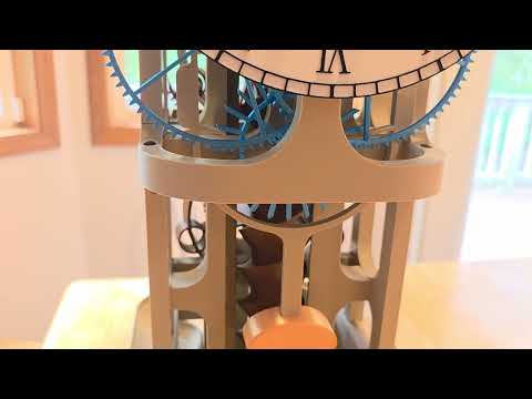
The escape mechanism is a deadbeat escapement.  I’d never made one of those before, but this one works quite well.  It ran immediately after I assembled the clock!  However, it only ran for an hour or so.  I took this slow-motion video to help me see what was going on.  Turns out the drop was too large onto the right-side pallet.  You can see the escape wheel bounce back after it drops onto the right pallet.
https://youtu.be/kyaZNrRNpNgYouTube video

You need some drop, otherwise, the pallet might hit the tooth of the escape wheel. That’s not a good thing either.  But too much drop wastes energy.  So, after adjusting that side of the pallet down just a bit, I got rid of the excessive drop, and things run great.  It’s been running for a couple of days now.

In this video, you can see the escapement running properly.  You can also see the adjustment screws in the last few seconds of the video up in the upper left-hand corner of the screen.  It's a very interesting pendulum design with the pallets built into the pendulum.  Steve made the pendulum easily removable, which facilitates loading the balls into the ball wheels to start the clock.
https://youtu.be/LIa_EcF9e-4YouTube video
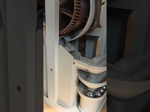
After a little more than a day, all the balls have released their potential energy to the clock and are now at the bottom.  To remedy this, Steve made a long ball screw that lifts them back up to the top.  Winding this clock is a noisy affair!  It's a long ball screw so the balls don't even start rolling out the top till about 24 seconds into the video!  :o
https://youtu.be/DXnYKqPwoDgYouTube video

All in all, a very fun, rewarding project.  I would highly recommend it if you have any interest.  Very fun, and quite cool to have running, if somewhat noisy! :)

Kim
crueby
Reply #10 · 14 Aug 2026, 23:24
Thats quite cool!  The big trick was making us think you were making a fusee  skeleton clock!  :Lol:


The ball clock is a really good design!
Dave Otto
Reply #11 · 15 Aug 2026, 00:01
That's pretty cool Kim!
How many hours will it run on a full supply of balls?

Dave
krt2
Reply #12 · 15 Aug 2026, 04:03
Thanks Chris and Dave!

Quote from: Dave OttoHow many hours will it run on a full supply of balls?

It runs 30 hours on 100 ball bearings, or 38 hours on 125 ball bearings (1.6 days).  That's about the max you can load onto the ramps.

He has also included a modification where you replace two of the gears with a different gear ratio that will give you 57 hours (2.4 days) with the same 125 balls. But he recommends starting with the lower gear ratio since that's easier to get running.  I may make the higher ratio set of gears and see if I can get that working too. Always good to have something to work on, right? :)

I'm also toying with the idea of modifying it to use an automatic electric motor winder that would kick in when the balls get low in the upper ramp.  I'd want to make it electromechanical, NOT using an Arduino or anything like that.  Little limit switches or something.  Somehow that sounds more appealing to me than making it electronically controlled.  But who knows.  I haven't really committed to that yet.  But it does sound like another fun sub-project  :Lol:

Kim
crueby
Reply #13 · 15 Aug 2026, 12:59
The rewinder ought to be a steam engine! Limit switches turn on a little compressor, or open a solenoid valve to your shop compressor. Off limit switch also blows a whistle?  :thinking:
Krypto
Reply #14 · 15 Aug 2026, 13:24
Great job!  Steve's clocks are always fun to make.  Somehow that clock looks even bigger in your video than on the webpage.  It's a monster!  I imagine it would be a great attention-grabber at any of the model shows.

On the ball winder, check out the "groups" at Steve's webpage as a few people have already done this.  One fellow used a 12V, 1 RPM motor/gearbox combo and it seems a clean mod.  Seems to be a lot of interest in this clock so I imagine Steve will release another clock based around a rewind motor, the big advantage being you will need far less balls to run the clock if it's always feeding them up.

Quick reply

Log in to reply.





