EPO - A Super-Simple Oscillator

Started by PaulR · 20 replies · 5,060 views

PaulR
11 Feb 2026, 17:47
While still trying to work things out for my next project, being tired of looking at CAD and not having had any time in the workshop for a few days, I decided to make a really simple wobbler from a plan found online. I've built a few similar engines in the past but never with a pivot at one end rather than in the middle of the cylinder, so for completeness, here goes EPO, the End Pivot Oscillator.

I turned the 0.5" square cylinder and port blocks to size and marked up for the various holes and the recess around the crankshaft that needs to be milled or filed away. Unless I'm really losing the plot, I think I spotted what would be a terminal mistake in the drawings straight away: the port in the cylinder is shown as passing straight through, meaning air would come in and go straight out without having any effect. Anyway, I drilled and reamed the bore, the hole for the 4mm pivot and the 5mm crankshaft (might stick a ball race in there, need to look at diameters of what I've got). I drilled a 6mm hole at the end of the cylinder where the arched slot will go and will probably saw/file the rest out. Also drilled that 2mm hole in the cylinder...but not all the way through!  :Lol:

The plan calls for 1mm radius bevels on all edges which I probably won't do because 1) I'm not sure I like it and 2) doing it accurately and uniformly on all edges would be tedious :Lol: I think I'll need to adapt the inlet connection a little bit as well to make it more airtight and suit the air line I have.
Log in to see this image
crueby
Reply #2 · 11 Feb 2026, 21:13
Don't think I've ever seen one set up as an end pivot, should do interesting things to the motion.  :popcorn:
Jasonb
Reply #3 · 12 Feb 2026, 06:53
I suppose you could think of an end pivot as the crank side of a double acting wobbler with the top half of the cylinder cut off. In which case the position of ports is similar and motion the same, only difference is this has the inlet above the piston as per a single acting.
PaulR
Reply #4 · 12 Feb 2026, 07:28
Quote from: JasonbI suppose you could think of an end pivot as the crank side of a double acting wobbler with the top half of the cylinder cut off. In which case the position of ports is similar and motion the same, only difference is this has the inlet above the piston as per a single acting.

Yes, it's just half a wobbler with the crank flipped over to the other side I suppose. At this scale the arc of the cylinder port can also be considered a straight line which makes things even simpler.

Thinking about trying to mill the aperture that the crank pin moves in using the vertical slide. The curved top is 6mm (as per the hole I've already put in) but I don't have a 6mm slot drill. Is a 6mm end mill likely to bind if the part is is fed across the bed then slowly advanced towards the headstock for each cut (I usually take no more than 0.005" at a time anyway)?
Log in to see this image
Jasonb
Reply #5 · 12 Feb 2026, 07:58
An end mill will do. It is only a clearance slot for the crank pin so the slight tendency for a 4-flute cutter to cut a bit oversize does not matter.

I'd go deeper per pass as it is only brass otherwise you just wear the corners off the cutter. 0.020" would be quite conservative
PaulR
Reply #6 · 12 Feb 2026, 08:38
Quote from: JasonbI'd go deeper per pass as it is only brass otherwise you just wear the corners off the cutter. 0.020" would be quite conservative

Cheers, I'll give it a whizz with some scrap first, see how it behaves.
PaulR
Reply #7 · 12 Feb 2026, 11:58
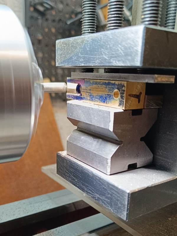
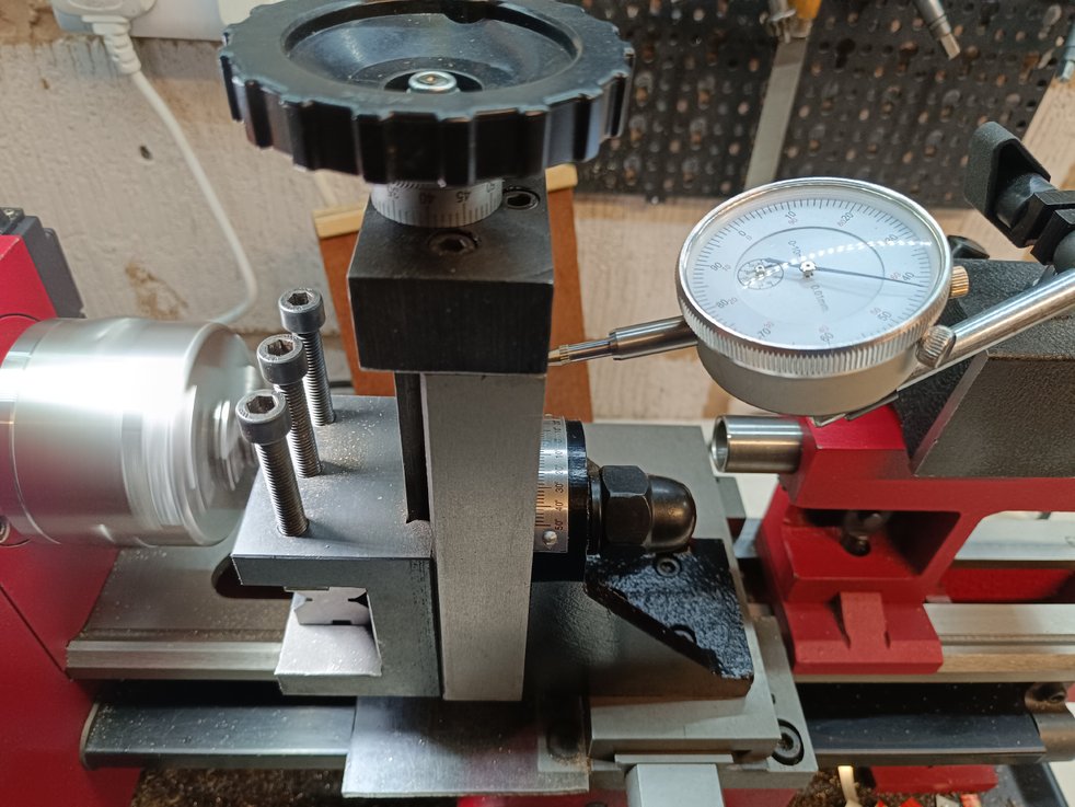
Decided to go straight to the business rather than muck about with a trial on scrap. Needed a bit of thought and playing Jenga to get the part in the right place but it seemed rigid enough. To align things I brought the carriage up and twiddled the dials until the end mill went into the hole. Still waiting on someone to 3D print a carriage stop/DTI holder for me, it occurred to me that I could get the same result by sticking a magnetic base/DTI on the tailstock and putting the plunger against the back of the slide. As the cut was deeper than the depth of the plunger I had to move the tailstock half way through the job but at least I could see what depth of cut I was putting on each time. Turns out that 0.015" was fine and is probably not far off what I was doing 'blind' rather than the 0.005" I mentioned above.

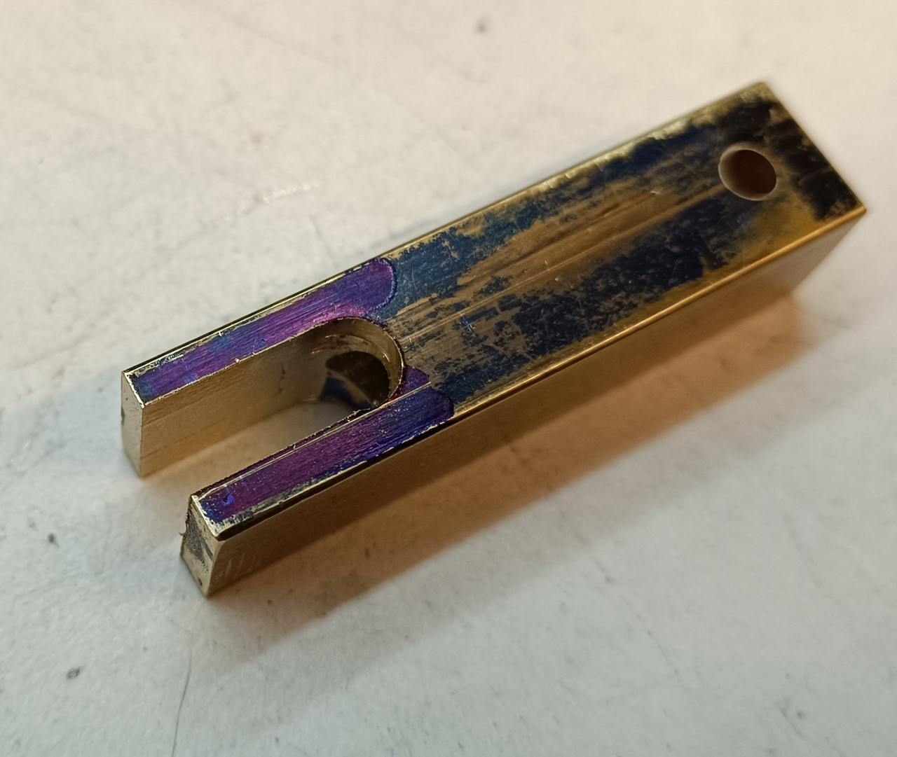
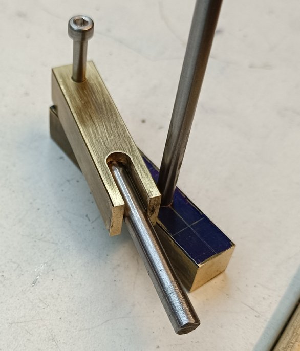
Everything went to plan except the slot was slightly offset compared to the bore. I'm sure the bore is as central as I could get it, the error is probably due to the drilled hole used to align the endmill being oversize. Maybe I should have made a reamed hole or perhaps relied on the endmill to form the rounded end instead and just used a pop mark for alignment. No big deal anyway, the error is around 0.4mm and was easily corrected with a file and the slot is only cosmetic. Overall I was very pleased to discover it worked as hoped for, next time will be better  ;D

The 'stack':


The 'cutometer':


After milling, the error is obvious:


After a bit of filing:
PaulR
Reply #8 · 12 Feb 2026, 14:50
While the milling slide was set up I thought I'd do the other bit of milling, a straightforward recess in the column. ! was really fortunate that this simpler set up left just a gnat's whisker above the vice jaws. I'll probably have neck ache tomorrow from the contortions required to see what was going on  :Lol: A bit of draw filing and some steel wool removed most of the machining marks.

Log in to see this image
PaulR
Reply #9 · 12 Feb 2026, 20:41
Drilled the port 'oles, deviated from the plan to make the inlet and made the combined piston/rod...

Log in to see this image
PaulR
Reply #11 · 13 Feb 2026, 14:43
Quote from: cruebyQuick progress!  :popcorn: :ThumbsUp:

Yep, thanks to it being so simple :D

Threaded a hole on the bottom of the column then spent ages sawing a 2" dia piece of steel to make the base. I've left it bigger in diameter and thickness than that on the plan so it'll be a bit better rooted and not be a wobbler that wobbles off!

Also made the crank; as the photo shows I ended up holding it by next-to-nothing (it's 3.5mm thick) but it worked out ok. I was aiming for a press fit on the shaft but somehow managed to take off just a tad too much so Loctite has come to the rescue. Tomorrow I need to run the diameter down a bit so it fits in the recess on the column or might go mad and shape it rather than leave it as a disc. I have a solid flywheel that I made then switched out for the last wobbler so I might be able to use that for this one - need to check diameter.


Log in to see this image
PaulR
Reply #12 · 14 Feb 2026, 20:45
Turned down the crank disc and decided to leave it at that as it's pretty much invisible anyway. Made a little split bush to hold the crank pin while threading and tidying up the ends, it worked great and saved getting any marks from the chuck jaws on this part which needs to be nice and smooth.

Connected up all the bits and hooked up the air line and after a couple of twiddles by hand it started running but promptly unscrewed the crank pin and fell apart  :Lol: I've now fixed that in place with Loctite so it should be ready to run tomorrow. Second picture shows the combined piston/rod and the cranky bits.

Log in to see this image
Jasonb
Reply #13 · 14 Feb 2026, 20:50
Just put the air in the other side so it runs the opposite way and tightens up the screw by itself :LittleDevil:
PaulR
Reply #14 · 15 Feb 2026, 07:38
If only life were so simple :Lol: the present exhaust is just a hole, I might make a pipe for it though.

Quick reply

Log in to reply.