



Chris's Un-Ransome Tree Feller

Started by crueby · 185 replies · 65,619 views

crueby
17 Aug 2024, 15:58
Back a couple years I attempted a model of the Ransome Tree Feller saw/engine, based on plans from an old magazine and pictures of a wonderful model someone else did. However, I was never able to get the funky twisted-rod valve mechanism working well, and gave it up to move on to other engines. The saw reciprocates, but there is no crankshaft or eccentric, more like boiler pumps. Since then, once in a while I gave the valve setup some thought, and finally came up with a version that I think will work well.

Its based partly on the linkage from boiler feedwater pumps, and partly on the long-link engines in sternwheeler riverboats. I didn't want to have the long rod with stops like a lot of feedwater pumps have, and the riverboat style linkage lets me get rid of that, though I'm still using the shuttle valve like in boiler pumps to move the main D valve for the cylinders back and forth. More details on it as the build progresses - I have it all drawn up in CAD and have had the CAD model simulate all the movements, so I'm confident it will work.

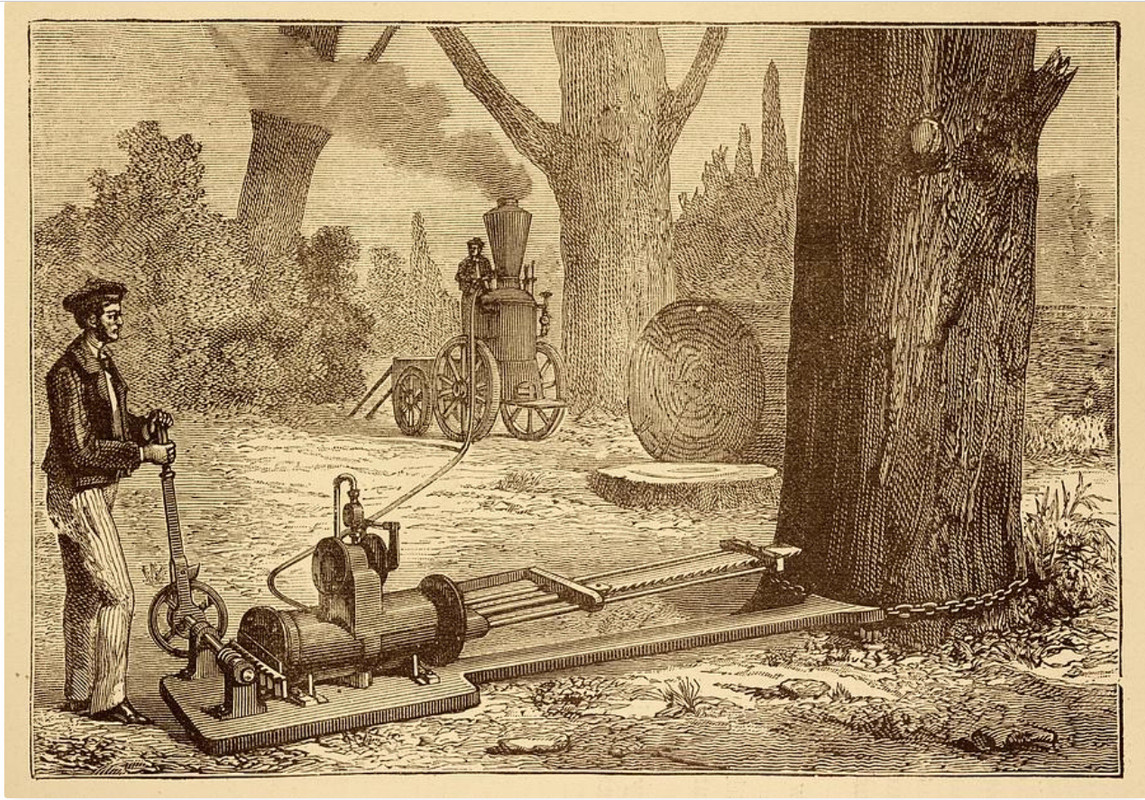
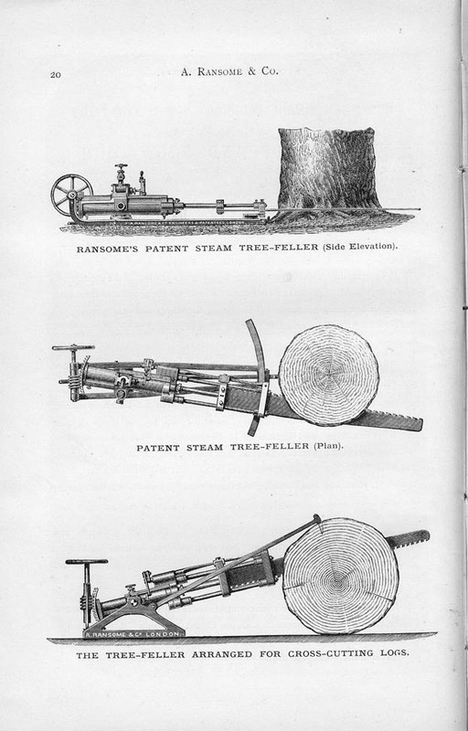
So, what the heck is a Ransome Tree Feller? Here are some pictures from the old Ransome catalogs. This first picture shows one in action, one end of the frame chained to the tree, with the operator turning a screw that turns the saw on a pivot in the middle of the cylinder to advance the saw through the tree. They powered them with small portable vertical boilers on sleds or wagons. Wedges would be put into the saw kerf to keep the tree from binding up the saw. Basically did the same job as chain saws do today, but before small gas engines were invented. These were produced for many years, and there are a few operating that show up at steam shows today.

This picture from their catalog shows different versions of the main frame but the same core cylinder setup. The bottom view, with the saw set up to crosscut logs already felled, seems the most useful to me, cutting logs into shorter lengths for transport.

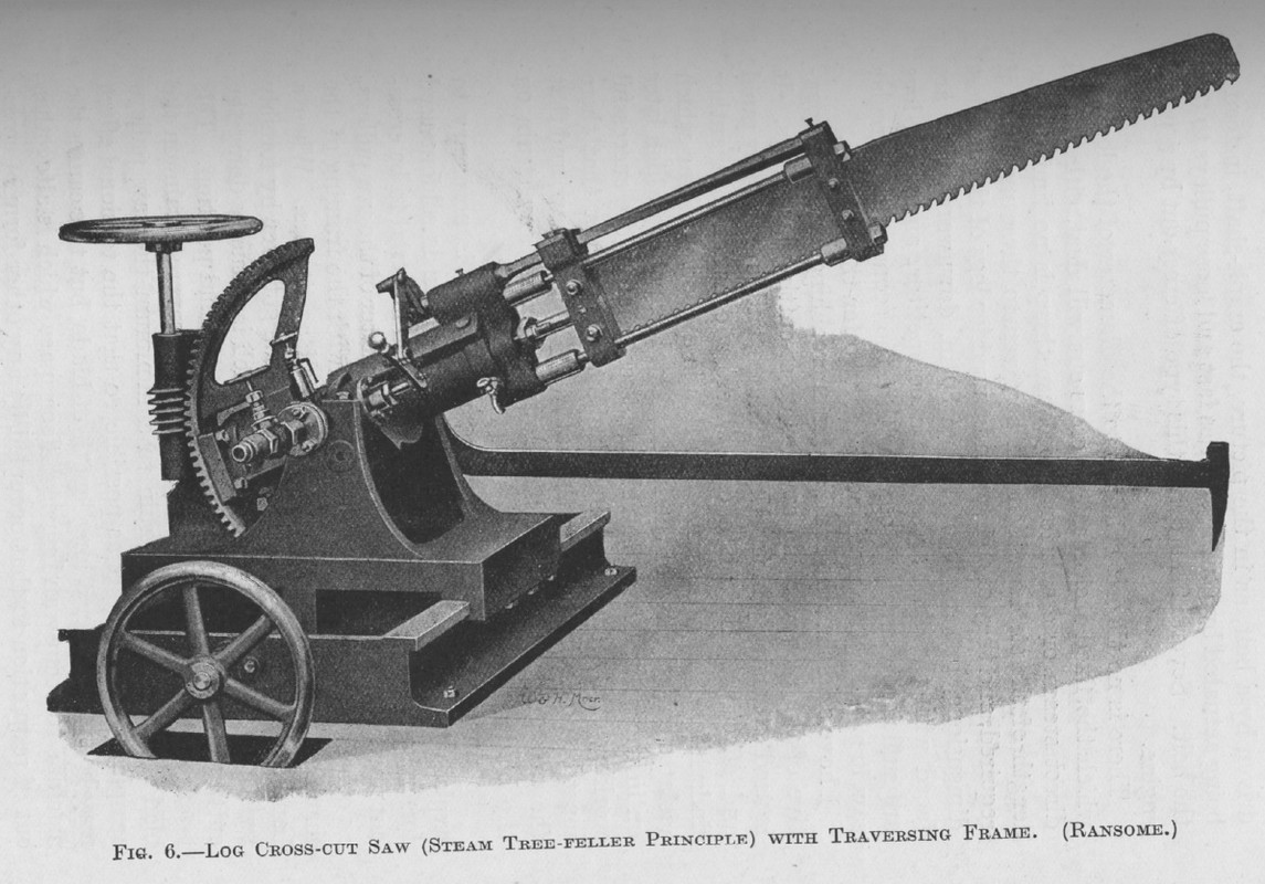
There was also this version of the vertical setup, with a more advanced base that allowed positioning the saw for specific lengths of cut in a factory setting:

And here is a screenshot from my CAD version of the saw with the modified valve linkages in place of the original twisted rod and rotary valve:
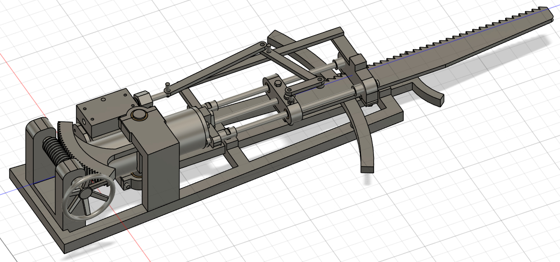
I've drawn up both the horizontal and vertical bases, will probably do the horizontal one.

So, thats where this build is going, time to start cutting metal. I dug out this chunk of brass from the 'scrap' bin, its a partial attempt at the high pressure piston valve housing from the Ohio engine build  don't recall why it was set aside but its the perfect size for this model, so its getting a second chance at being used.
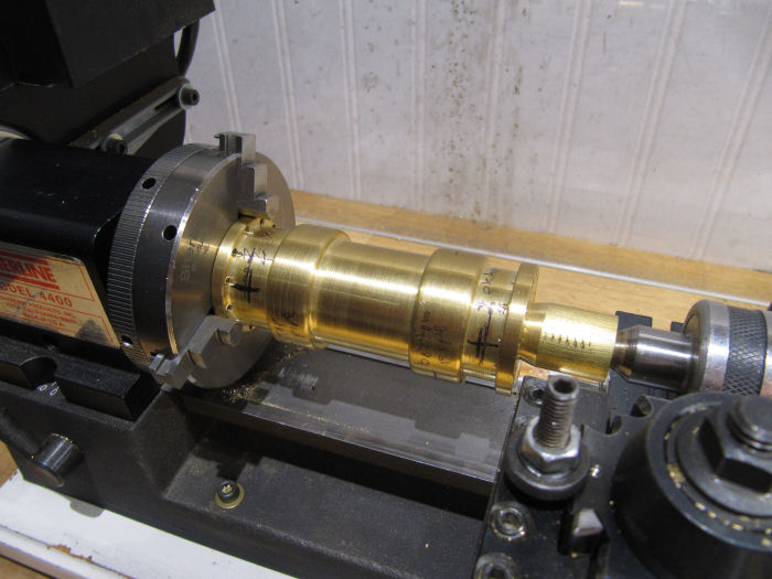
First, it needs to be turned down to a cylinder. You can see a short length of smaller bar at the end by the live center - the hole already in the part was slightly larger than the OD of the center, so I needed this piece as a filler.
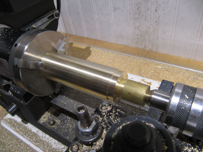
The bar was turned down, and a small shoulder added at the end which will face the saw blade - need to put a larger flange there for holding the guide rails for the blade. Then, set up the steady rest and bored the hole out close to the final 3/4" size:
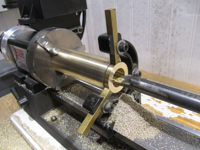
The bore was finished with a 3/4" reamer to ensure a constant hole size all the way down the long length of the cylinder. The reamer shank would not fit in a drill chuck, so I had to use a 3-jaw chuck held on the tailstock with a morse taper adapter. Also had to remove the steady rest to get the cross slide out of the way, the shank on this reamer is not long enough to reach past it and all the way down the cylinder length.
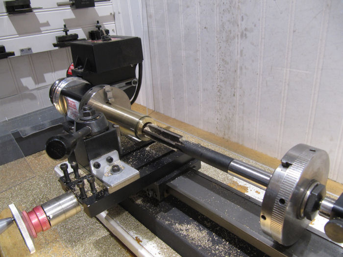

so, the core of the cylinder is done, next I'll cut down some larger diameter bar stock for the end caps/flanges, as well as a ring that will go over the center to hold the trunnions and the steam chest. Away we go on a new build!
:cheers:
Michael S.
Reply #2 · 17 Aug 2024, 17:27
I'm happy that it's continuing.
I would have needed a saw like that. I had to cut down a birch tree at my parents' house today. It was a bit tiring.

Michael
Log in to see this image
krt2
Reply #3 · 17 Aug 2024, 17:28
Looks like a great start (or re-start?) of a new project!  :ThumbsUp: :popcorn:

Kim
crueby
Reply #4 · 17 Aug 2024, 17:46
Quote from: JoLooking forward to seeing if this one works.  ;)

Jo

Me too!  :Lol:
crueby
Reply #5 · 17 Aug 2024, 17:46
Quote from: Michael S.I'm happy that it's continuing.
I would have needed a saw like that. I had to cut down a birch tree at my parents' house today. It was a bit tiring.

Michael

Thats a lot of tree, especially  over structures! 
crueby
Reply #6 · 17 Aug 2024, 17:47
Quote from: KimLooks like a great start (or re-start?) of a new project!  :ThumbsUp: :popcorn:

Kim

Restart, not reusing much if any of the first attempt, maybe the guide rail parts.
crueby
Reply #10 · 18 Aug 2024, 12:50
Quote from: stevendavisInteresting project! Will any of the parts be cast?
No, all made from bar stock. Some will be silver soldered together.
crueby
Reply #11 · 18 Aug 2024, 14:32
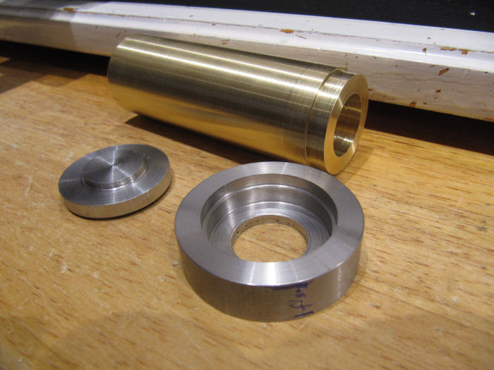
Started shaping down the rest of the cylinder parts. The small cap on the left is for the rear of the cylinder (the end away from the saw blade), and the larger one with the bored out center is the flange for the front end of the cylinder. The front end flange is larger since it needs to support the guide rod assembly as well as the piston rod.


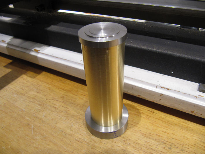
Here they are test fit on the cylinder. The rear cap will bolt on lie normal, studs in the cylinder end going through the cap. The flange will be cross pinned onto the cylinder along with some loctite, and it will hold the studs for the outer cap.


Before maing the front cap or drilling any holes, I need to make another sleeve, this one for the middle of the cylinder to tae the trunnions the cylinder will pivot on, plus the connections to the valve chest and the traversing gear out the rear.
crueby
Reply #12 · 19 Aug 2024, 14:36
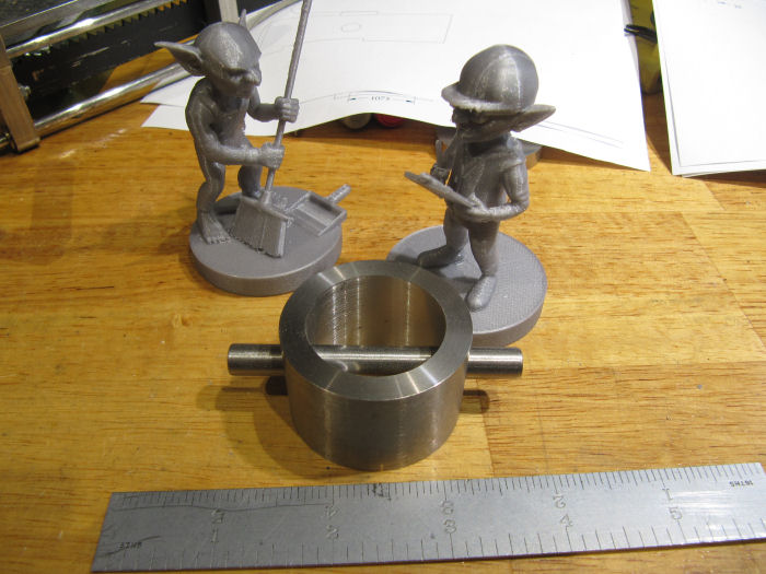
Got the center ring bored out to fit over the cylinder this morning. It will hold the trunnions to pivot the cylinder, and also hold the valve blocks and the swing gear.


Drilled the hole for the trunnion bar, wanted it drilled through in one setup to ensure the two ends are in line with each other. I'll silver solder the bar in place, then cut out the center section. Hmmm, for now it looks sorta like a London Underground sign! The new shop elf trainees are checing it out.


crueby
Reply #13 · 19 Aug 2024, 19:53
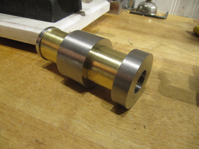
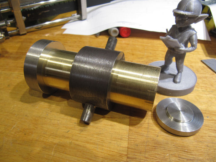
Got the trunnion bar silver soldered into the ring - took two sessions, by the time the first side was up to temperature and the solder flowed in, the flux on the other end had burned off and some soot built in. Cleaned it up in the pickle and redid the second end. Then trimmed out the center on the mill, straight cuts across, then put it on the lathe to turn the nubs left over down flush on the inside. Here it is slipped over the cylinder again.

Next I can mill the flats on the ring for the other parts to mount to, and start drilling/tapping all the holes to hold everything together.

Quick reply

Log in to reply.