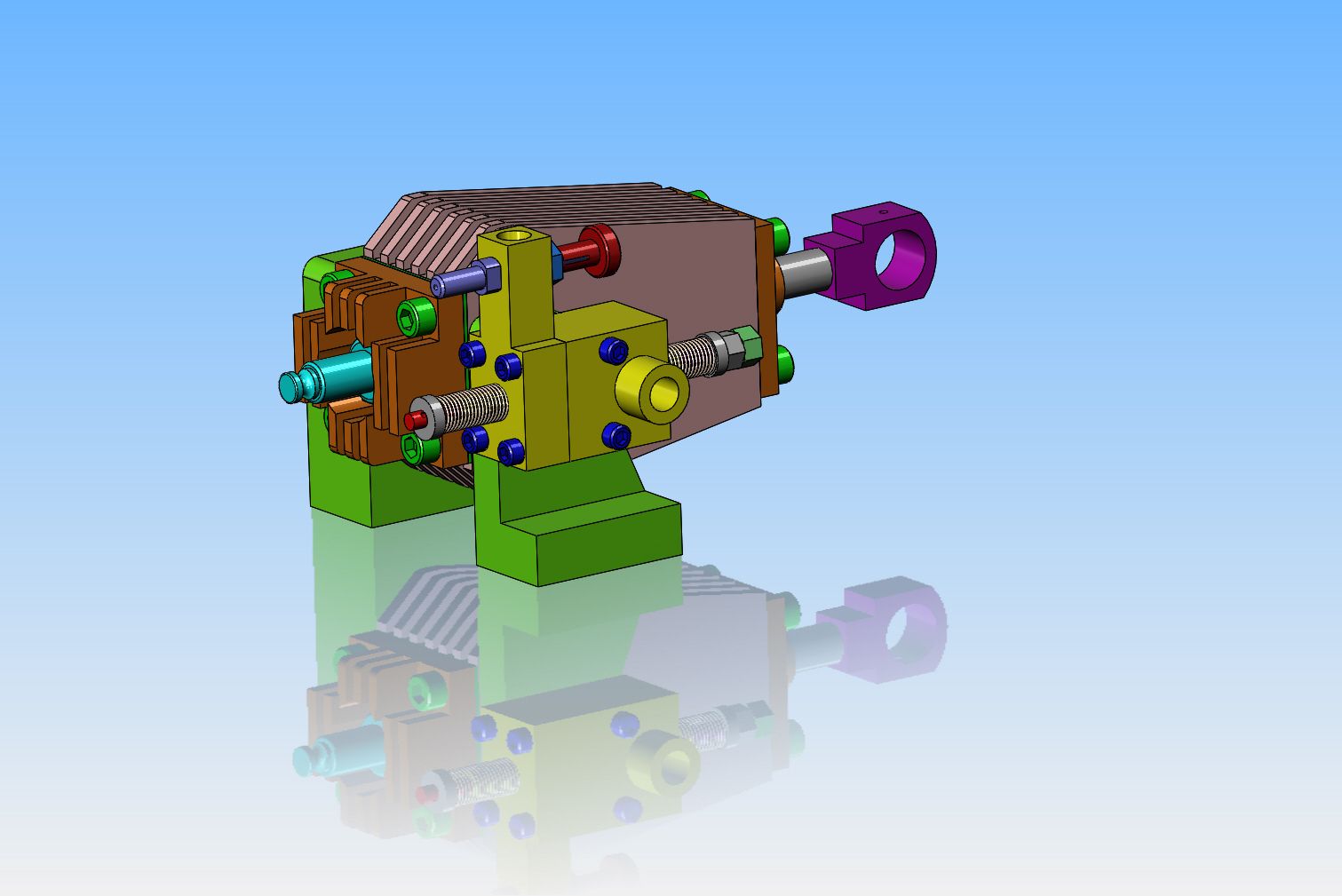
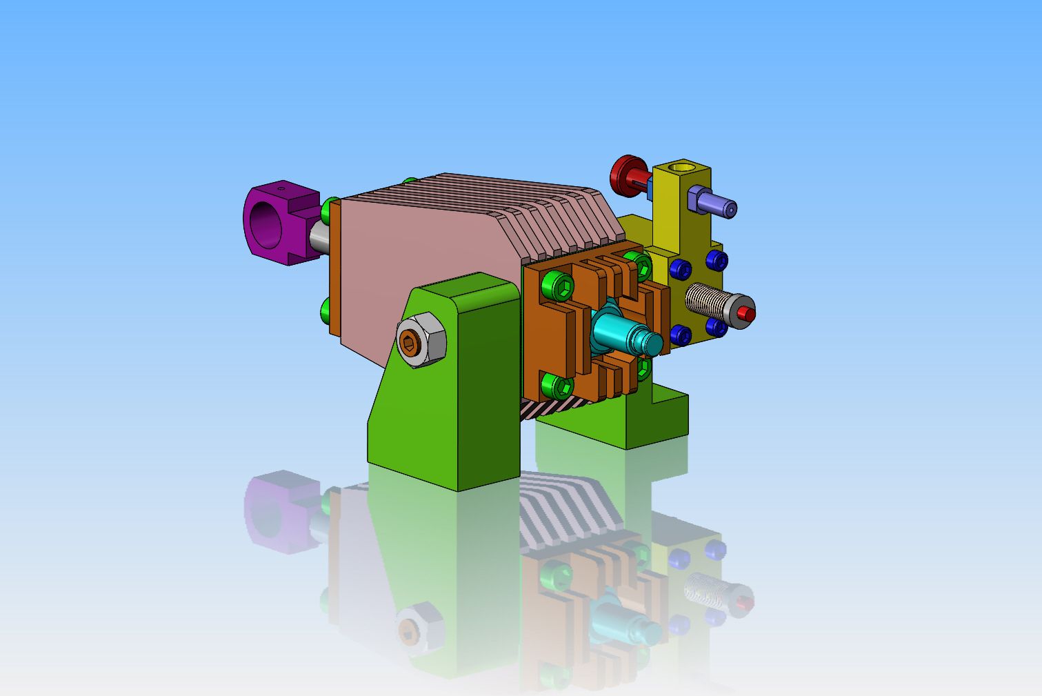
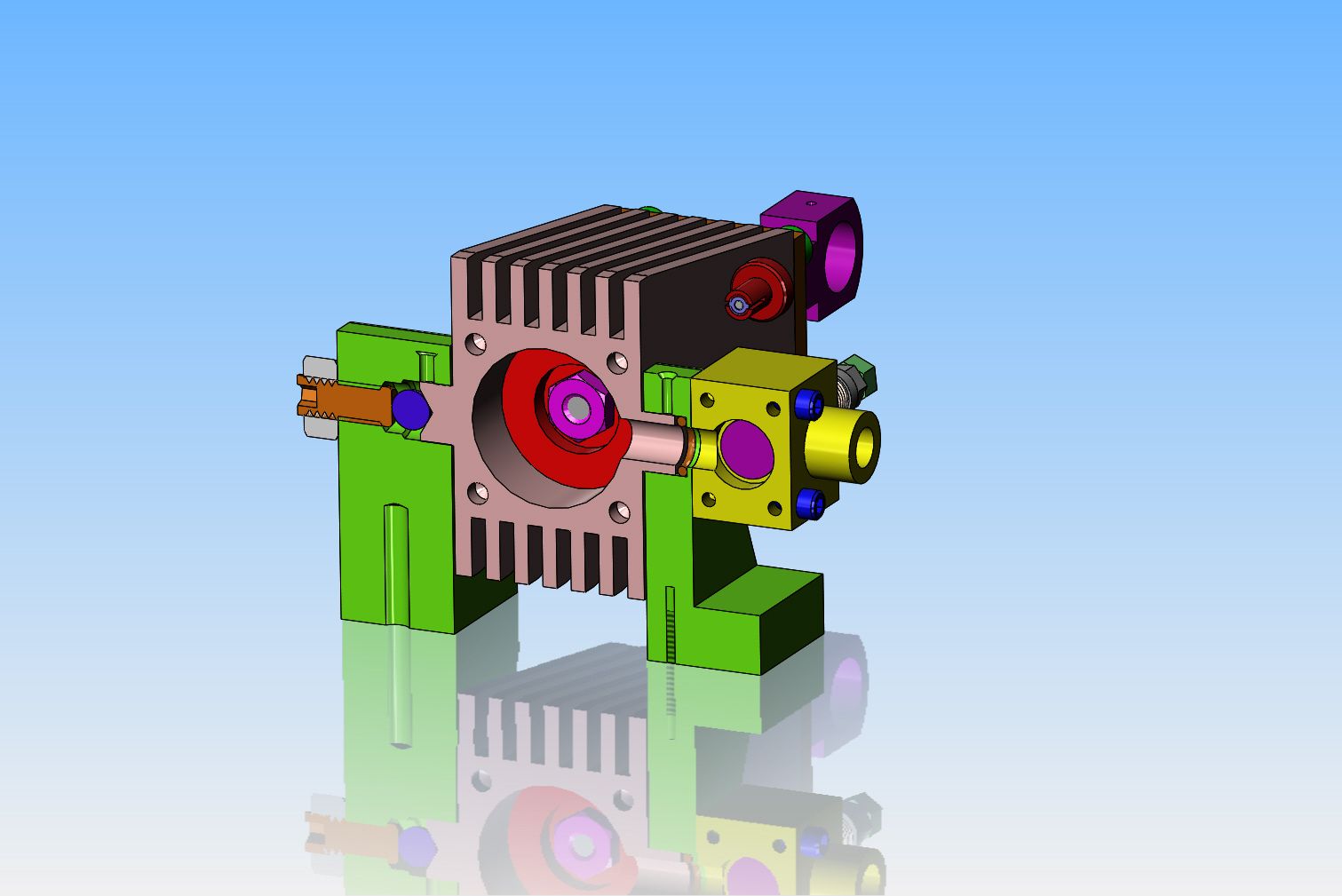
So now, after another four hours of modelling, it becomes clearer how this can be. The green support stanchions are fixed in position to a base. On the non carburetor side, there is a steel ball bearing setting in the recess at the end of the stub-shaft on the side of the cylinder. Then there is a 1/4" set screw resting against the outer side of the steel ball, locked in position with a 1/4" hex nut. On the carburetor side, there is a 1/16" cross section rubber o-ring (I will probably use Viton because of the heat.) setting between the end of the boss on the cylinder side stub-shaft which is hollow, and a flat bottomed counterbore in the green stanchion. This provides an air tight seal. The carburetor is bolted to the outside of the stanchion, and doesn't move. I will probably stick a paper gasket between the carburetor and the stanchion, but for now I haven't shown it. In one of the pictures, you can see the intake valve on the same end as the sparkplug--it is an atmospheric intake valve and requires no valve lifter. The exhaust valve is on the other side of the carburetor block, and will be operated by a lifter. There is a single hole in the side of the cylinder, and as in the Webster engine, it serves as both intake and exhaust port. You can see the (purple) head of the exhaust valve in the cross section.