





Another Adventure in Hot Air

Started by PaulR · 76 replies · 3,423 views

PaulR
17 Sept 2026, 18:54
I've made four Stirling engines, two of which just about worked, the other two were 100% failures so it's time to try to improve the score.

This will be another side-by-side horizontal engine, just a little bit bigger than the last two and having water cooling in the plan from the start. As usual, I'll be recycling whatever materials I can, hopefully folks won't find the materials or my crude methods too offensive  :Lol:

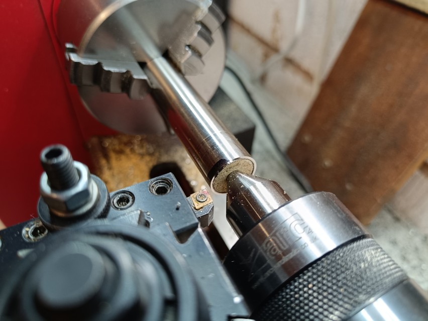
For the displacer cylinder I'm using a piece of 19mm (0.5mm wall) steel of some sort from an old clothes rail. I used a wooden plug at each end to allow me to face it to length (using the wrong tool so as to just miss the live center!). I'll silver solder a cap at the hot end and a square flange to mount it at the other. The water jacket will probably be soft soldered in place.


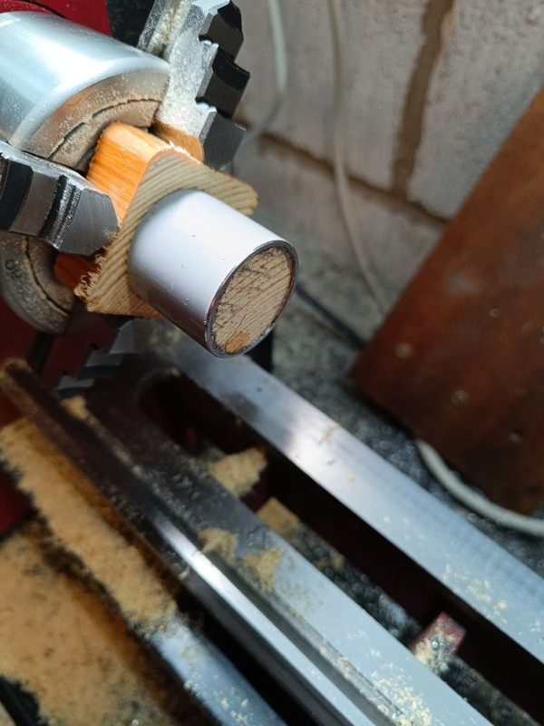
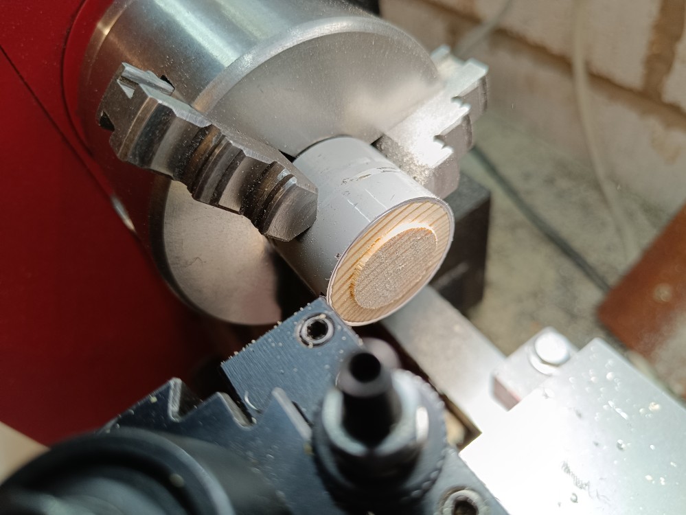
For the water jacket, I'm using a piece of 30mm tube from an old garden parasol stand. As it's quite short I thought it might be ok to face the ends without any support. It turned ok except at some random points the seam was incredibly tough and immediately blunted the tool and dented the tube. After stupidly trying this on two short lengths, I decided to make a wooden mandrel from an old kitchen table leg (or maybe it was my old granny's wooden leg I dunno). This went swimmingly, there was a bit of resistance at the seam in places but not enough to cause any issues. After facing one end I sawed off the remaining bit of square leg and flipped it into the 3-jaw to do the other side. It's now spending the evening smeared with Nitromors to remove the coloured coating. The wooden plug will stay in for some time yet as I need to drill three holes; one for the air tube to the power cylinder and two for water connections.


Spinner21
Reply #1 · 17 Sept 2026, 20:39
Best of luck with this one Paul, take your time and get everything lined up well and get the best finish and fit with your power cylinder and piston.
Andy.
PaulR
Reply #3 · 18 Sept 2026, 19:20
Couldn't find any aluminium to use for the displacer so decided to make from solid mild steel. I got the wall thickness down to about 0.6mm and the end caps have about 1mm inside and 0.75 outside. The top cap has a boss inside to connect the rod - rather than thread this beforehand I decided to make a slightly undersized tapping hole (to remove the excitement silver soldering a closed vessel would elicit :lolb:) which will be tapped with the finished displacer held in the lathe to keep it as concentric as poss. Fingers crossed it won't be too heavy.
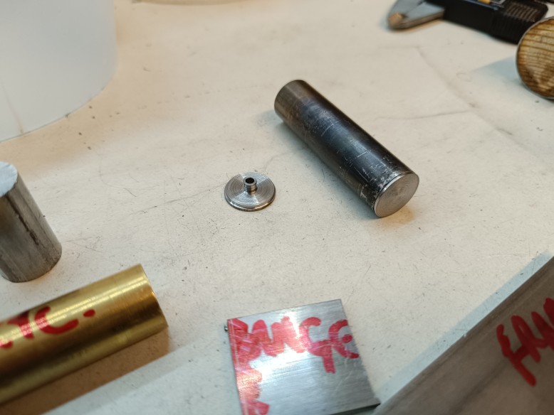
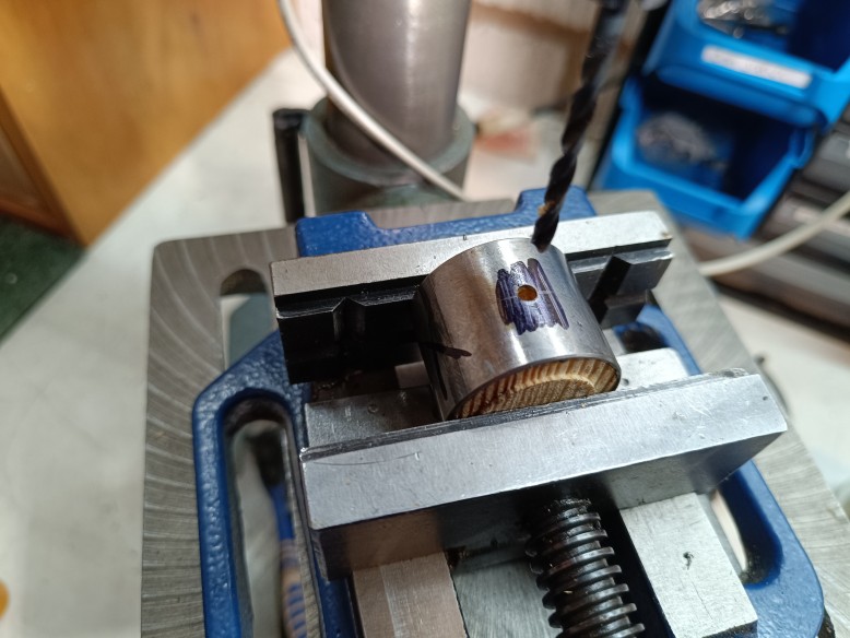
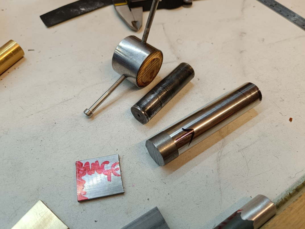
I drilled and tapped the water jacket connectors M4 - there was just about enough thickness in the wall to get some thread on. I'm not sure if the planned 2.5mm hole through the connector will be enough to feed sufficient water through, if not I could always make these holes bigger and just solder the connectors on.


Here's the state of play with temp screws in the jacket, the displacer all soldered up and a piece of steel turned to fit in the hot end and yet to be thinned down.


Minh Thanh
Reply #5 · 19 Sept 2026, 02:28
Quote from: PaulRCouldn't find any aluminium to use for the displacer so decided to make from solid mild steel. I got the wall thickness down to about 0.6mm and the end caps have about 1mm inside and 0.75 outside.

  Given those specifications, it seems quite heavy.
I chose the lightest possible materials (aluminum, in my case) to make the displacer.
Friction is a crucial factor determining the success or failure of a Stirling engine project, and the weight of the components plays a role in that.
Your engine might be much bigger and more powerful than mine, but if it were me, I'd still choose aluminum.
Only by following the best course of action—and when the engine is not running—can I easily identify other causes for the engine's failure to run. - Of course, that's my way  ;)
crueby
Reply #6 · 19 Sept 2026, 02:33
How much does the materials  choice impact heat transfer, and the behavior of the  engine overall? Are there certain  parts better made in aluminum or  copper vs steel for heat transfer reasons? Or is that not a concern?
:shrug:
Minh Thanh
Reply #7 · 19 Sept 2026, 05:05
Quote from: cruebyHow much does the materials  choice impact heat transfer, and the behavior of the  engine overall? Are there certain  parts better made in aluminum or  copper vs steel for heat transfer reasons? Or is that not a concern?
:shrug:


  I cannot give you a precise answer regarding exactly what you need, as I am neither a materials expert nor a model engine specialist.
  I will speak based on my personal experience.
I have constructed power cylinders and pistons using cast iron, stainless steel, and steel. For the displacer, I always choose aluminum for one simple reason: it is the lightest among the metals I can easily source. I once built some Stirling engine entirely out of 6061 aluminum—piston, cylinder, body, and displacer....—though the shafts were steel, of course; it ran very well.
Regarding heat transfer, different materials naturally have different thermal properties. Consequently, in the Stirling engines I build, I typically separate the hot and cold sections, joining them with a thermal insulator (such as Teflon)- all my engines have 8mm power piston, I strive to optimize their performance as much as possible. A larger engine generally produces more power... though I can't say for certain. Regardless of the engine size—big or small—I always stick to my guiding principle: minimizing friction as much as possible by reducing the weight of the components and weight negatively impacts power output; an engine might run, but it won't be able to handle that weight . Personally, I prioritize these materials: for cylinders—brass, steel, cast iron, or stainless steel; for pistons—aluminum (since it's lightweight) or cast iron. The choice of materials depends on your specific goals—  you want the best or simply need it to run.
Spinner21
Reply #8 · 19 Sept 2026, 12:22
I would generally agree with Mihn Than on his choice of materials, although I have made displacers from mild steel with good success although the engines are somewhat larger. For power cylinder and piston I prefer cast iron  as the running friction is very low and thermal expansion is equal, in low temperature engines the use of graphite is good but it is very delicate.
Andy
PaulR
Reply #9 · 20 Sept 2026, 13:44
Well, we'll see about the displacer, it's not that hard to make another one if it turns out to be a problem.

Meantime, I made the connectors for the water jacket and made the ends from pieces sawn from an old cash tin (it was the thinnest steel sheet I could find). Drilled a hole through the two pieces, glued them together, mounted them on a mandrel with supporting washers each side and turned the OD. Put them against the 4-jaw chuck face and used a silver steel rod in the tailstock to centre the hole then bored them out to size. Here are the parts assembled ready for soldering although I have to make the flange to go at the cold end first. I didn't have any brass sheet to make these parts so I'll just have to make sure they're well dried out after use.

I intended to thin down the cap on the end of the displacer chamber after it was soldered in place only to find it wouldn't fit through the aperture in the 3-jaw chuck so I'll have to do that in the 4-jaw which has a bigger 'ole in the middle.
Log in to see this image
Minh Thanh
Reply #10 · 20 Sept 2026, 14:26
I was planning to bring up a few more points, but...
Everyone has different preferences and choices...
Let's get back to your project !
  :ThumbsUp:
PaulR
Reply #11 · 20 Sept 2026, 17:31
This afternoon I made the flange to fix the displacer body to the frame although the holes still need to be threaded. Also got the frame itself and the brass flange to fasten the cylinder to the right dimensions.

Log in to see this image
PaulR
Reply #13 · 20 Sept 2026, 19:05
Quote from: Sanjay FLooking good, how big is that, I can't tell?  :popcorn: :ThumbsUp:

The square bit at the front in the first photo is 1" square.
PaulR
Reply #14 · 21 Sept 2026, 19:18
Got the holes drilled through the frame and the corresponding holes threaded on the displacer chamber flange and the alignment looked good so proceeded to the next step, making a threaded hole for the displacer rod bush and boring out the back of the frame it to accommodate the displacer.

A slight problem with the dimensions emerged: I'd planned on a 6mm threaded bush but the small boring bar I have needs at least an 8mm hole. It was either make the threaded hole bigger or grind a small boring bar from HSS so I decided on the latter. To save lots of grinding I used a tool that I'd previously customized. It had much more overhang than ideal but it didn't take much doing to get some decent cutting angles on it and it worked great. There was a bit of chatter at the shoulder but I took it steady, enlarging by 0.003" increments at a time (from 5mm up to 19mm  :o) ) until it gave a nice push fit.

Log in to see this image

Quick reply

Log in to reply.