Another Simple Hot Air Engine

Started by PaulR · 63 replies · 3,425 views

PaulR
29 Aug 2026, 15:35
Off we go again! This time I'm trying to make a hot air engine loosely fashioned after a Robinson type but a lot smaller, simpler and made from bar stock so basically nothing like one of those  :lolb:

Once again I've started making parts before the plan is barely begun so there will probably be some deviations. I made the displacer from 1/2" tube and silver soldered in some enc caps. As it's going to be vertical I decided to reduce the weight by having the rod screw into an internal boss at the top only. All looked good until I put it into some hot water to check for leaks; there was just a tiny bubble or two at the bottom end but as I agitated it, it became worse and finally the bottom fell off  :ROFL: That's the difficulty of soldering from the inside - I could see the solder had run but not where, turns out it was not where needed! Oddly, the top end which was done completely blind, was completely sealed. So I re-did the bottom and now it's fine. I put it in the lathe held by the rod and found there was some visible run out at the far end. I think I should have just drilled a small hole prior to soldering then left threading the hole until last and put the sealed displacer in the lathe to do it. Never mind, I doubt that it's bad enough to foul the cylinder.

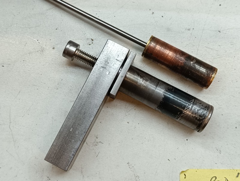
I made the displacer cylinder from 5/8" solid, turning down the outside to 15.5mm and boring the inside to 14.25mm. I had to do each half separately which is why there's a bit of a ridge halfway down on the outside... can probably smooth that away though  ;D
Log in to see this image
Dave Otto
Reply #1 · 29 Aug 2026, 15:43
Off to a good start!
What I usually do on my displacer cylinders that are made from solid is to bore the inside to size, then make a mandrel that is a snug fit in the bore. slide the cylinder onto the mandrel and hold it in place with the live center and a pressure pad.
This way it is relatively easy to create very thin walls which are desirable for this part.

Dave
PaulR
Reply #2 · 29 Aug 2026, 17:05
Quote from: Dave OttoOff to a good start!
What I usually do on my displacer cylinders that are made from solid is to bore the inside to size, then make a mandrel that is a snug fit in the bore. slide the cylinder onto the mandrel and hold it in place with the live center and a pressure pad.
This way it is relatively easy to create very thin walls which are desirable for this part.

Dave

Thanks Dave. I've got a wood mandrel I made for some of the displacer material (used for cylinders on the last rotary valve engine) so I used that but should have done the same for the displacer cylinder. What do you use for the pressure pad and how do you hold it?
Dave Otto
Reply #3 · 29 Aug 2026, 17:34
Hi Paul

Nothing fancy, I just use a small piece of aluminum round stock, face both ends and center drill one. It only needs to be long enough to accommodate the center drilled hole. I suppose you could use wood for that too if you wanted.
The job that you are turning will dictate what diameter and length you use.

Dave
PaulR
Reply #4 · 30 Aug 2026, 07:17
Quote from: Dave OttoNothing fancy, I just use a small piece of aluminum round stock, face both ends and center drill one. It only needs to be long enough to accommodate the center drilled hole. I suppose you could use wood for that too if you wanted.

Sorry Dave, I don't quite follow. Is the tube you've bored longer than required so you can hold it and the mandrel in the chuck with the pad at the other end then turn down everything (including the pad) to the required length like this?
Log in to see this image
Spinner21
Reply #5 · 30 Aug 2026, 11:38
Hello Paul, I don't want to steal Dave's thunder but I think what he means is that you put a bar of material in the lathe and turn a stub mandrel that your embryo displacer will just slide onto but slightly shorter so that when you push the previously made end cap with the running centre it will trap your displacer on the mandrel and provide enough drive to the displacer to enable you to lightly turn the outside diameter.
Also if you are turning the displacer (or displacer chamber) from solid bar you could bore it out and then part it off so that you leave one end closed, does need a bit of careful measurement though.
Andy.
PaulR
Reply #6 · 30 Aug 2026, 12:00
Quote from: Spinner21Hello Paul, I don't want to steal Dave's thunder but I think what he means is that you put a bar of material in the lathe and turn a stub mandrel that your embryo displacer will just slide onto but slightly shorter so that when you push the previously made end cap with the running centre it will trap your displacer on the mandrel and provide enough drive to the displacer to enable you to lightly turn the outside diameter.
Also if you are turning the displacer (or displacer chamber) from solid bar you could bore it out and then part it off so that you leave one end closed, does need a bit of careful measurement though.
Andy.

Thanks Andy, that makes perfect sense  :ThumbsUp:
PaulR
Reply #7 · 30 Aug 2026, 15:49
Time to make the part that holds everything together. First I made the collar or flange which will be soldered to the displacer and drilled some small holes so I can mark through those to get the right positions for the screws.

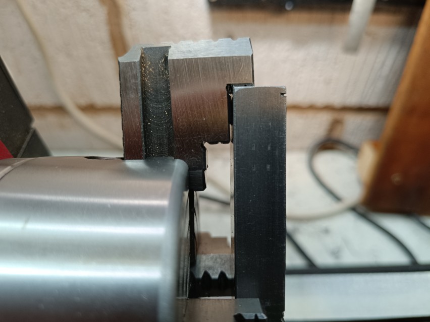
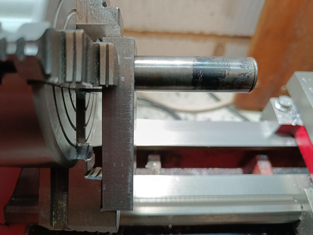
Next, mounted the bar in the 4-jaw which was just about possible with one jaw on the outside. However, as I was spinning the chuck I noticed that the outside jaw was nothing like square to the face of the chuck. I took the part out and checked that jaw - it was in securely but it could be wobbled all over the place! I'm guessing it's just down to it being a cheap chuck supplied with the lathe.


Anyway, I put the part back in, got it centred with a floating centre, then checked it was perpendicular to the bed - it wasn't quite but a gentle tippy tap with a mallet soon had it looking right. I crossed everything and hoped it would stay put despite that one jaw still being at a ridiculous angle.

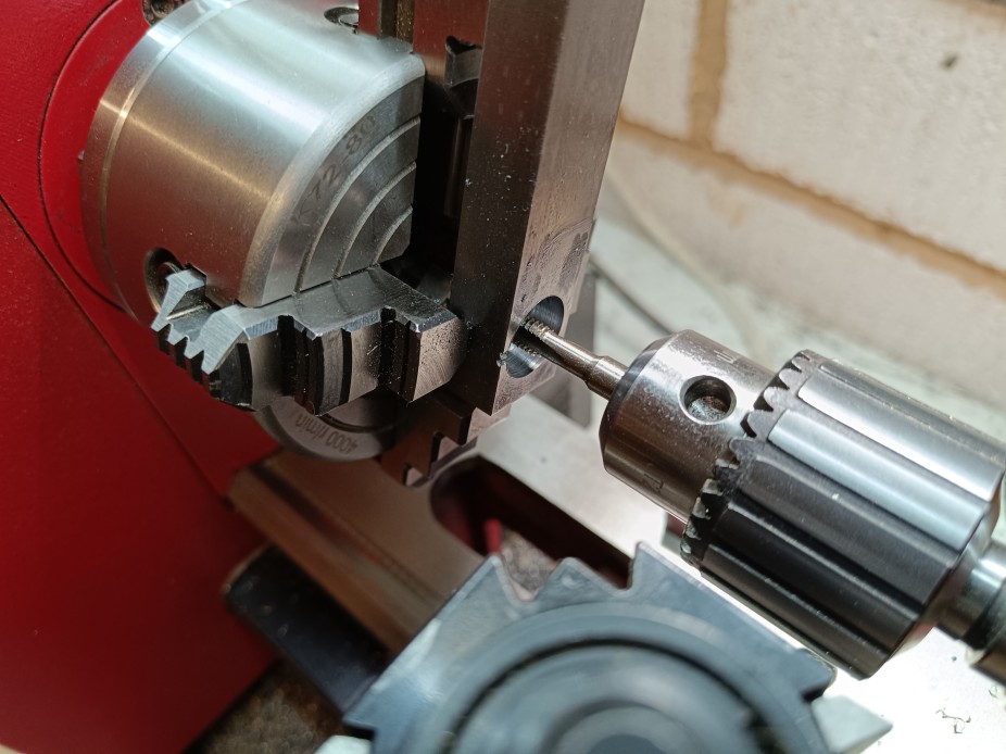
Drilled through at tapping size, then 7.5mm deep with a 10mm drill then bored it out to 15.5 to fit the displacer. One thing I've learned with my puny boring bar - when I get within 0.25mm of the required diameter I just put on repeated cuts without adjusting the crossslide at all until I get a good fit - that shows how much flex there is in the tool! Anyway that went well, the displacer is a nice tight fit and most importantly looks pretty square.  :whoohoo:


The final step while mounted was to do the thread for the guide bush.


The parts placed together:


With a screw in the hole for the bush:


Next job on this part... drill and tap holes for the screws, drill and plug the air passages. In the meantime need to crack on with the plan so I know where the various holes for the cylinder support and bearing need to go.

EDIT: ignore the nasty saw cuts visible at the tapping stage, it's the only piece of bar I could find and they won't show when assembled  ;D
PaulR
Reply #8 · 30 Aug 2026, 19:11
Made the holes for the screws to hold the displacer cylinder which meant I could then open out those in the collar and solder the two parts together. Also made the brass bush but I'm not 100% happy with it. I used a 2.8mm drill and reamed to 3mm but it seems a bit loose. I might remake it and try a 2.5mm hole before reaming.

I've been having a bit of a mare with centre drilling on the lathe recently. Every now and then the drill doesn't centre properly and I end up with a hole that has a little pip in the middle but I'm damned if I can see what's causing it. The drill bits are fine, the faced surfaces seem fine and it only happens sometimes which maybe rules out tailstock alignment. Any suggestions?
Log in to see this image
Spinner21
Reply #9 · 30 Aug 2026, 19:29
Paul that problem is usually caused by the drill chuck/tailstock being out of alignment with the lathe spindle.
Check that your drill chuck is located properly in the tailstock ie clean the taper socket and drill chuck  shank and check the centre drill  is located properly in the chuck jaws.
If that doesn't cure the problem you may have to check the alignment of the tailstock spindle although if this is a recent problem I would also clean the bedways and the base of the tailstock first.
Andy.
crueby
Reply #10 · 30 Aug 2026, 20:37
Second what Andy said. I've had that issue sometimes with chips/dirt under the tailstock base. Sometimes I've found my center drill was getting dull and had it from that, sometimes just speeding up on the headstock when center drilling helps. For critical holes, I prefer to drill undersized and use a boring tool to get to final dimension, though that is not practical for all sizes/depths.
PaulR
Reply #11 · 31 Aug 2026, 07:27
Thanks both, I'll have a look later and give all the potential problem areas a good clean.
PaulR
Reply #12 · 31 Aug 2026, 08:59
Had a look sooner rather than later. There was some swarf living on the tailstock locking plate but the ways were clear. Inside the chuck looked ok, but I gave it a gentle tap and wiped inside as best I could anyway, and it was secure on the taper. I faced off a bit of brass and tried the smallest center drill I have - it went off course. I faced off some more and tried the biggest one and the same happened. I took the chuck off and checked inside the sleeve and that seemed ok as well. The only other thing I could think off was removing the threaded stub from the end of the taper - I'd added that when I first got the lathe because the taper was frequently getting stuck when trying to eject it. I tried again and this time the centre drill worked normally. I switched to a piece of steel and repeated the face/drill operation for each of four sizes of center drill and they all worked fine. I'll see how it goes.

As a test, I decided to modify the displacer to try to eliminate the run-out so I drilled and threaded the other end (the centre drill behaved impeccably!) and plugged the original hole. It seems better, fingers crossed the plug will have sealed it properly.


PaulR
Reply #13 · 31 Aug 2026, 13:38
Next challenge was the long (50mm) air passage. I originally thought 2.5mm dia would do it but when I looked at the drill bit and the depth required I realized I'd need to go up a notch so used the 3.3mm tapping size drill so I could plug the end M4. I thought I'd drill it in the lathe as my pillar drill isn't great but it wouldn't fit within the chuck and there was far too much overhang for my liking. So fingers crossed and try it in the drill. As it progressed I had to pull the bit further and further from the chuck and start it within the work. Thankfully it worked out fine, you can just see the top of the temporary plug at top and the hole emerges under the punch mark. Phew!

Log in to see this image
PaulR
Reply #14 · 1 Sept 2026, 19:00
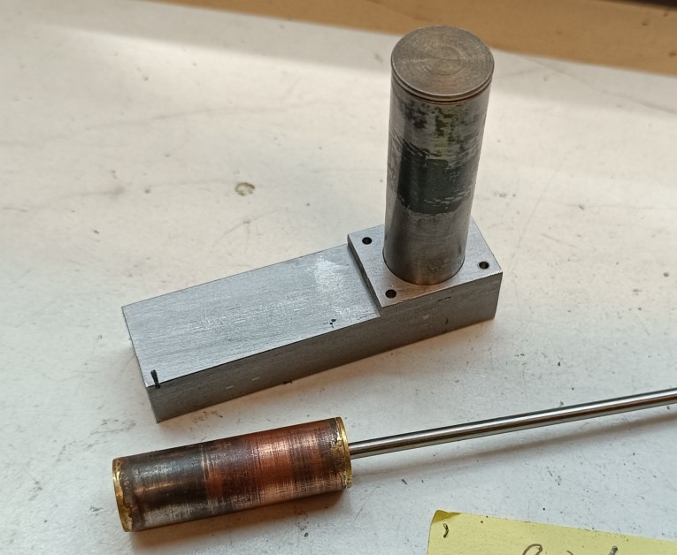
Made some blocks with holes in  :lolb:

First pic shows the unplugged air passage in the bottom part with the drill showing the route up to the cylinder. Second photo view from other side with displacer cylinder down at the bottom and super-long temporary disp. rod above. Everything seems lined up ok but I'm not convinced this is a sensible design as there seem to be too many places where leaks might occur. Might need some gaskets, sealant and o-rings - we'll see. I'm planning on having tall legs with the lower part angled outwards for stability (if I can make four the same!) and suspended between these (somehow, have figured yet) a sheet of 1/4" heat-proof board.

Log in to see this image

Quick reply

Log in to reply.