3D printed 1/16 scaled RC rotating tracked dumper

Started by ddmckee54 · 52 replies · 25,925 views

crueby
Reply #30 · 19 Jul 2025, 15:53
Interesting way to do it, never thought to use zero top/bottom layers!  I would have drawn the grid outlines in CAD and extruded the shape directly. Lots of ways to do everything!
ddmckee54
Reply #31 · 20 Jul 2025, 00:54
crueby:

That was my first thought too, but even if I used a linear pattern array it would still require a lot clean-up work around the pattern edges.  This way the slicer does all the work, you draw the outline in CAD and extrude that shape as thick as you want it and you're done.  EASEE-PEEZY  And if you want a larger/smaller grid pattern, you just change the slicer infill percentage - you don't need to redraw anything.

I think you could even get a close approximation to a sheet of diamond plate using this, if you play with the slicer settings.  I'd print the sheet thin, say 0.4-0.8mm, since this will be glued/bolted onto something else.  You'd print enough bottom layers that you'd only have 1-3 infill layers and no top layers.  You could probably even get by with a single perimeter wall.

Don
Last edit: 20 Jul 2025, 01:29 by ddmckee54
crueby
Reply #32 · 20 Jul 2025, 01:07
Quote from: ddmckee54crueby:

That was my first thought too, but even if I used a linear pattern array it would still require a lot clean-up work around the pattern edges.  This way the slicer does all the work.  And if you want a larger/smaller grid pattern, you just change the infill percentage - you don't need to redraw anything.

Don


Clever!
ddmckee54
Reply #33 · 20 Jul 2025, 03:51
It does work for diamond plate.

Both of these guys were printed from the same STL file, that's 0.6mm thick, with 2 bottom layers, 1 infill layer, and 0 top layers.  The guy on the left was printed at 30% infill, while the guy on the right was printed at 75% infill.  They're both clearly visible at arm's length, but the 75% looks too small - I probably should have used 60%.
ddmckee54
Reply #34 · 21 Jul 2025, 14:40
The plastic pooping robot continues to poop out a pile of grey parts.

What we have here are the main parts of the lower rotating assembly.  Clockwise from the right we have, the main frame, the slew gear - with the slew bearing installed, the slew gear spacer, and the slew ring clamp.  The big hole in the main frame is where the slip-ring will live.  When it gets printed, the upper slew bearing clamp will live in the space below the slew bearing and above the main frame.  The slew ring clamp keeps the slew bearing from being pulled out lower rotating assembly, while the upper slew bearing clamp stops the upper half of the rotating assembly from being pulled out of the slew bearing. The key-hole shaped slot gives me access to install/tighten the screws that hold the upper slew bearing clamp to the upper center frame - also yet to be printed.

The plastic pooping robot has a LOT more grey parts to poop out yet, so I better get it going on the next batch.

Don

Last edit: 21 Jul 2025, 14:48 by ddmckee54
wagnmkr
Reply #36 · 22 Jul 2025, 11:55
I took your idea for no top or bottom layers and used it to experiment a bit. I have a need for some mini chain link fencing as well as some metal ramps and walkways in an industrial diorama. This is the result of playing with infill percentages as well as infill patterns. By cutting off one edge of the frame, it does a fairly accurate impression of a chain link fence (if it was the right colour and shape)

Cheers, and Thanks for the idea  :cheers: :cheers:

Log in to see this image
ddmckee54
Reply #37 · 22 Jul 2025, 19:48
wagnmkr:

Glad to be of help.  Now, if they'd give just us an infill pattern where WE could control the grid spacing, we could really get creative with our industrial grid making.

Don
Last edit: 22 Jul 2025, 19:54 by ddmckee54
ddmckee54
Reply #38 · 25 Jul 2025, 14:43
I made a door for the cab, I know I told the the Muse I WASN'T going to make a working door... and I DIDN'T!  I made a door skin with some fake hinges that got glued on to the side of the cab.

It looks better in real life, the flash washed out all the shadow lines.  But the flash Does let you see inside thew cab better, you can even see the E-Stop button on top of the control panel.
ddmckee54
Reply #39 · 28 Jul 2025, 14:22
In the last couple of days I've been busy figuring out how I could modify a 13 rpm 3D pen's extruder drive, with a worm gear output for the final drive, into my slew motor.  Also figuring out just how much other stuff I'd need to modify, because SOMEBODY didn't bother to figure this out BEFORE he slapped everything together in the assembly drawings.

Fortunately, none of the modifications were extensive.  The 3D pen extruder has a worm output gear, and a straight cut gear, both are pressed onto what looks to be about a 1.5mm shaft.  What I am starting with looks very similar to this.

I had to order a small gear puller set that will allow me to pull the gears off the shaft, and press everything back together when I'd done with the modifications.  I'll need to make a new output shaft, one that's nearly 20mm longer than the existing shaft.  I've no doubt that I'll need to order some stock to make that shaft.  I also need to go from the 1.5mm shaft to a 4mm shaft, for the 14T GT2 pulley that I'm using for my slew gear pinion gear.  I've got some 5mm stock I'll use for that.

I discovered that some how, somewhere along the line I had changed my mind about exactly where I was going to put the slew motor.  I started out with the planned location being on top of the platform.  I think it probably changed about the time I decided to put a seat, and an operator, and a control panel in the cab.  Because some Doofus didn't 3D model this change at that time, when I got around to it - I was in trouble.  By that time I had received the 14T pulley, which was also about 12mm longer than I was expecting - I can only get rid of about 4mm of that 12.

BUT... I've still got to bury the slew motor gear box, which is 10mm thick, into the upper frame - which is 12.7mm thick.  AND, has 5mm deep wiring tunnels dug right where the slew motor needs to go.  I can sink it about 5mm into the upper frame. but I need to gain at least another 5mm somewhere - maybe more.  I added another 5mm to the height of the spacer ring that positions the slew bearing, modeled the 14T pulley as short as I could get it, and checked the 3D model for interference.  I still had interference between the tracks and the bottom of the slew pinion - so I added another 2mm to the spacer ring.  I now have 1.7mm clearance between the tracks and the slew pinion as the pinion rotates over the tracks.  (That's good enuf for Gub-mint work!)

Between the slew motor debacle, and the GT2 pulley being 12mm longer than expected, I had to add over 9mm to the space between the upper and lower frames.  It's starting to look a little ODD.  I think I can lose some of that extra height by eliminating the upper and lower slew bearing clamp rings, which are both 3-4mm thick.  The upper clamp ring holds the inner race of the slew bearing to the upper frame, while the lower ring holds the outer race to the lower frame.  The rings are each held on by six M3 button head screws.  If I eliminate the rings, and use the just button head screws - and flat washers - to hold the races in place, I can probably lose about 6-7mm of the extra 9 that I added.  Which should help to eliminate the too tall look.  But doing that means I need to change the positions of the pockets for the heat set inserts in the lower frame - which is already printed.  (Nope not changing that one, maybe just the upper clamp ring?  We'll see.)

Don
Admiral_dk
Reply #40 · 28 Jul 2025, 17:12
All part of the Fun and Games that are going on while Creating ....  :embarassed:

But I'll agree that a good amount of this might have been prevented during the CAD proces ..... Not that this happens to me ....  Nope  :old:  :noidea:

Per      :cheers:
ddmckee54
Reply #41 · 29 Jul 2025, 02:47
Quote from: Admiral_dkAll part of the Fun and Games that are going on while Creating ....  :embarassed:

But I'll agree that a good amount of this might have been prevented during the CAD proces ..... Not that this happens to me ....  Nope  :old:  :noidea:

Per      :cheers:


Yeah, right... Now try pulling the other leg.

Now that I've slept on it, I realized that I literally can't eliminate the clamp rings without a MAJOR redesign of the entire rotating assembly, AND reprinting the lower frame.  The lower frame is about a 10 hour print.  The one place where I can save space, without too much extra effort is the 14T GT2 pulley - this guy.

Sorry about that, the image from Ebay was bigger than I expected. 

Anyway... this guy as you see it, is over 18mm tall.  For some reason I had it in my head that I needed to keep the set screws.  If I eliminate the thinner upper flange, and the 9.5mm thick set screw flange, all that's left is the tooth section - which is  all I need.  I can just Loctite that onto the output shaft and I'm in like Flynn.  Plus I can save myself up to 11mm in height.  I'm going to work on it some more tonight, I may be adding another view of the assembly drawing later.

Don
Last edit: 29 Jul 2025, 03:06 by ddmckee54
ddmckee54
Reply #43 · 29 Jul 2025, 16:26
"The best laid plans of mice and men"....  Boy oh boy, that guy REALLY knew what he was talking about.

I worked on the rotating assembly for several hours last night before I threw in the towel, I didn't accomplish much.  Let's look at my version of an 800 pound gorilla.
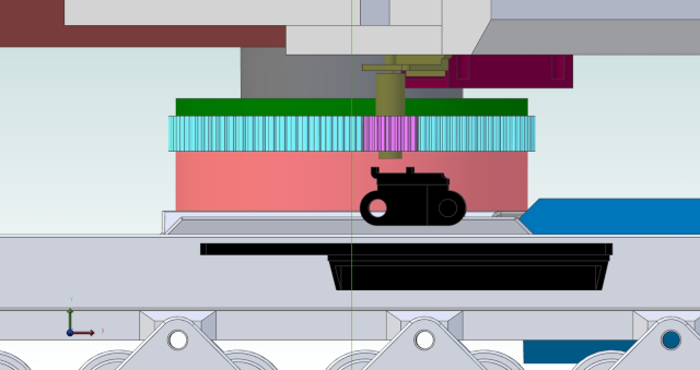
What you're looking at is the heart of this machine, it's what I call the rotating assembly.  The major players in the rotating assembly are the following:
1) The upper center frame, that's the dark grey piece in the upper center. The dark brown piece is one of the upper frame rails, these rails are bolted to the upper center frame and support everything on the top half of the machine.  Inside this part is where the slip-rings that feed power to the main drive motors live.
2) The slew gearmotor, that's the olive drab object.  It's a repurposed 3D pen extruder drive.
3) The slew motor clamp, it's the dark purple bit.  This keeps the slew motor in place, and allows about 1mm of motor adjustment for pinion mesh.
4) The slew gear pinion is the light purple object in the center.  The slew gear pinion is a modified 14T GT2 timing belt pulley.  Numbers 1-4 make up the top half of the rotating assembly.
5) The slew gear is the cyan colored object behind the slew gear pinion.  Not shown is the slew bearing, it lives inside the slew gear, the inner race of the bearing is clamped to the upper center frame, and the outer race us a press fit in the slew gear.
6) The pinkish object is the slew gear spacer.  The clamp that holds the inner race of the slew bearing to the upper center frame lives in a space inside this spacer.  Six M3 bolts will keep the clamp attached to the upper center frame.
7) The dark green object above the slew gear is the slew gear clamp.  Six M3 bolts will go through the slew gear clamp, the slew gear, and the slew gear spacer, to keep these parts firmly attached to the main frame. (That' the light grey object at the bottom.)

In real life, what you are looking at is MAYBE 100mm wide by 50mm tall.  The slew gear pinion is a modified 14T GT2 timing belt pulley.  I initially thought that I could eliminate the flanges on this pulley and gain about 11mm of space.  Not so much, there are still 2 problem areas. 
Problem area #1 - There is about a 1mm gap between the dark purple slew motor clamp, and the dark green slew gear clamp.  No matter where it is in its' rotation, about 2-3mm of the slew motor clamp overhangs the slew gear clamp.  No extra room here to eliminate.
Problem area #2 - The black object directly below the slew gear pinion is a track plate.  Twice in its' rotation the slew gear pinion will swing over the track plates.  Only about 1-2mm of the pinion will swing over the plate, but it does swing over it.  There's currently about 2mm of clearance, again nothing extra to eliminate.

I spent several hours working on this last night, and other than making some pretty pictures I didn't get much done. 

Sooooo.... PICTURE TIME!
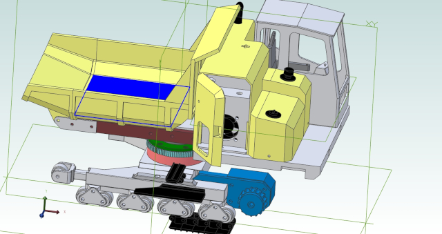
Ignore the dark blue in the dump bed, I didn't realize I had a surface selected when I exported this image.

This is another, and better, view of what's under the hood in the engine bay an tank areas.  It's a cross-section view with all but about the lower 20mm of the engine bay and tank walls removed.

I just now noticed that the work platform in the foreground is not correct.  The angled part of the platform should be to the front.  This is a 2 piece assembly, and I'm going to have to remember to build them as mirror images, not duplicates like they are now.

Don

Admiral_dk
Reply #44 · 29 Jul 2025, 18:19
I feel at bit Dumb - but I can't visualize the problem, when I look at your 'Prints' / drawings .... They all seems to clear each other ....

Per        :cheers:

Quick reply

Log in to reply.




