JCvdW

Full Member · Somerset West, South Africa · Joined Sept 2020 · Last active 2d ago
Full MemberMember
Message

About

“Somerset West, South Africa”

Signature
There is no planet B ...

Recent posts

All posts
  • In topic · 26d ago
    Thanks Riedoux313 for the kind words!

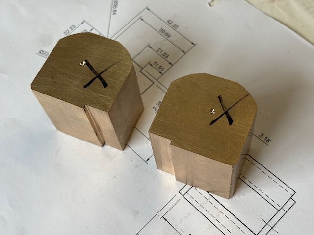
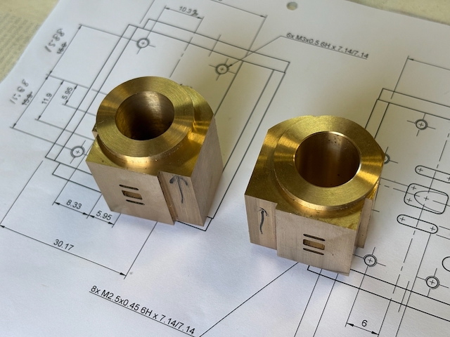
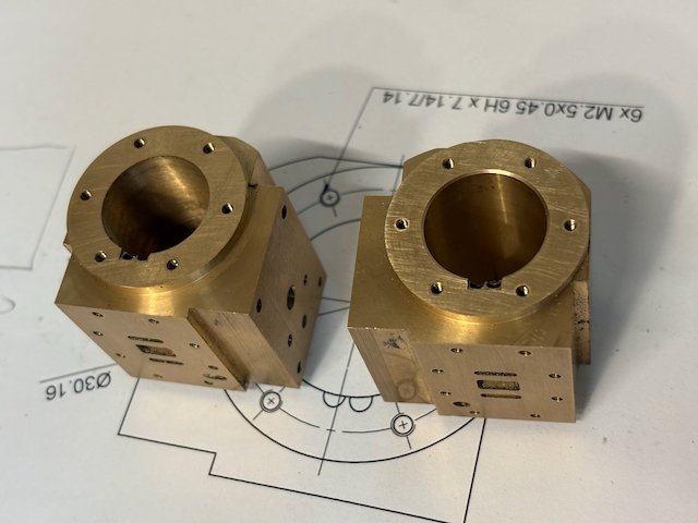
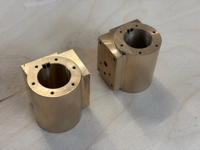
    Due to various other commitments, progress has been slow lately. But the phosphor bronze cylinders are finally complete.

    Below are a few shots along the way.

    After rough shaping:


    Bored and faced with steam ports:


    Screw holes and steam passages complete:


    Cylindrical surfaces machined on the lathe as suggested by Kozo:


    While working on the cylinders, surface rust started appearing on some of the mild steel frame components . It will not be possible to paint the frame in the near future, so the components were treated with a phosphoric acid based rust remover. It quickly removed the rust and covered the surface with a layer of iron phosphate. The components were thoroughly washed and dried afterwards. According to ChatGPT the iron phosphate layer is relatively stable and provides a good surface for later painting. Any comments/advice on this will be much appreciated.

    I am now off to the UK to visit the kids. Hopefully this will include a visit next week to the annual Midlands Model Engineering Exhibition!
  • In topic · 10 Aug
    Thanks Kim for the comments. It was particularly satisfying to see the enthusiasm of the local club members when they saw another live steam loco being built. It does not happen that often any more. At least not in these parts of the world.

    Quote from: cruebyExcellent!  That's a  major milestone.


    Thanks Chris. I guess the next major milestone will be running on compressed air, prior to taking on the boiler...

    Quote from: Prowler901I really need to update my post on my A3 progress...


    Todd, please update your post! Your work is both inspiring and humbling!

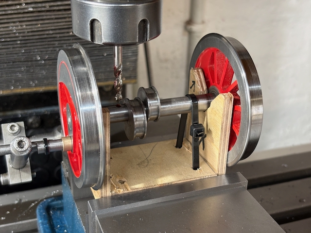
    I still had to drill small dimples in the rear axle for the grub screws of the pump and lubricator eccentrics. The quartering jig came in handy to hold the rear wheel assembly for drilling.


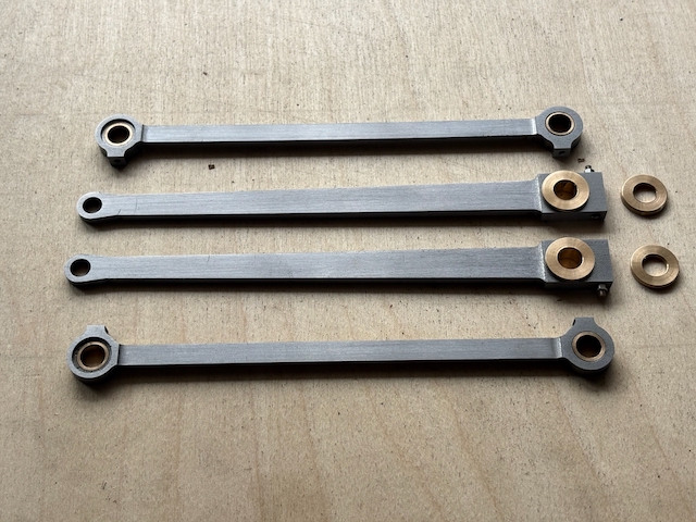
    After a couple of mishaps, the side and main rods are now complete.


    I am still waiting for an M2 die to arrive before I can complete the top half of the dummy cotter pins.

    In the mean time I have noticed rust appearing on the tender wheels. The rods and valve gear motion are now also unpainted mild steel. This begs the question - what is the best way to prevent these parts from rusting? At the time, I sprayed the tender wheels with clear 2K paint, but this clearly worn off when running on the rusty club track. I am thinking of oiling everything and then store it (even the tender) in a sealed plastic bag with some silica gel.
  • In topic · 14 Jul
    Kim & Roger, thanks very much for the kind comments!

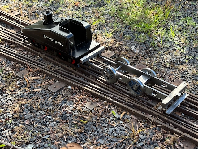
    Before painting and quartering the drivers, I thought it a good idea to visit the Western Province Live Steamers and verify that the engine and tender actually fit on their 3.5 inch track. They graciously allowed me to push it through a switch or two, and it rolled through without a hitch!


    The red 2K automative paint used on the tender was heat tested in the kitchen oven. It lost a bit of colour at 250 deg C, but there was no sign of it coming off at all. It should be more than suitable for the drivers.

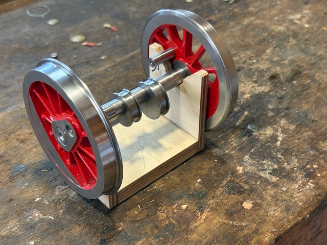
    After painting, the front and rear drivers were quartered in a wooden jig that was cut with my CNC router. The drivers were glued to the axles with Loctile 638 retaining compound.


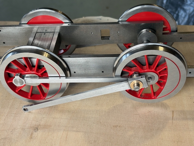
    Before proceeding any further, the accuracy of the quartering had to be checked. The holes in the side rods were located and drilled using Kozo's ingenious jig. With the bronze bushes inserted in the side rods, quartering could then be checked ... and with the side rods installed on both sides, the drivers would not move at all!

    Putting the driver assemblies back onto the quartering jig revealed the problem. Neither of the assemblies accurately fit the jig! There was a bit of play between the jig and the crank pins of the rear drivers, while the axle of the front drivers did not touch the 90 deg notch of the jig on one side at all.

    To redo the quartering, one of the drivers had to be removed from each axle. Fearing possible paint damage or warping, I did not want to use heat to weaken the Loctite. The assemblies were taken to a local engineering workshop, where the drivers were easily removed undamaged using an arbour press.

    To ensure accurate alignment during quartering, the axles and crank pins must be constrained in the jig as far as possible. Holes were drilled in the base of the jig for cable ties that can hold the axle and crank pins securely in place while the Loctile cures. The quartering jig was also held in the bench vice for more control during assembly.
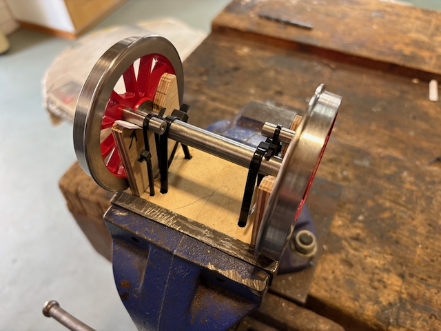


    To my relief, this solved the problem! The connected drivers now smoothly turn as one!

    https://youtu.be/kfwEToaDSdEYouTube video
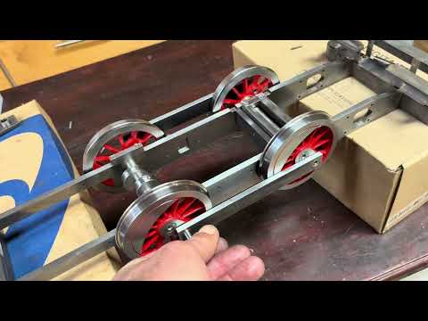
    Time to shape the side rods!
  • In topic · 29 Jun
    Elegant indeed!
  • In topic · 29 Jun
    Thanks for the comments Kim! I still remember following along as you fabricated your drivers. What a feat, and they came out great! At the time I could not even spell "silver solder" yet.

    I closely followed Kozo's instructions to machine the drivers.

    After the second chucking:


    And after completing all the lathe work:


    The drilling jig that was used to accurately drill the crank pin holes came in handy later to hold the pump and lubricator eccentrics to locate and drill the holes for the set screws.


    And finally the drivers, axles, eccentrics, crank pins and side rod pins are complete. Could not resist putting them all together for a family shot:


    The 11mm axles were turned from 12 mm silver steel. It took a few attempts to hit the correct diameter for a snug fit in the drivers and axle boxes. Using wet and dry sanding paper to remove the last 30 micron turned out to be the answer. This was also the technique used for the crank pins, which were turned from the scrapped axles.

    Next up are painting and quartering the drivers. But I first need to test the 2 component automative paint that was used on the tender, to see if it can handle to heat of the engine.